heat sink

A radiator and heat sink technology, which is applied in indirect heat exchangers, heat exchange equipment, electric solid devices, etc., can solve the problems such as the inability to fully uniformize the heating of the heat pipe group, the inability to fully improve the cooling characteristics, and the inability to exert the cooling characteristics. Achieves the effect of improving the cooling performance, preventing the increase of the size of the radiator, and improving the degree of freedom

Active Publication Date: 2021-02-02
FURUKAWA ELECTRIC CO LTD
View PDF4 Cites 0 Cited by
  • Summary
  • Abstract
  • Description
  • Claims
  • Application Information

AI Technical Summary

Problems solved by technology

However, there is a problem that if the flat parts of the heat pipes are arranged side by side in the vertical direction, the heat receiving area of ​​each heat pipe will be reduced, so the thermal resistance will increase, and sufficient cooling characteristics will not be exhibited.
[0007] As mentioned above, if the heat pipe group formed by a plurality of heat pipes is thermally connected to the heating body, the heat in the heat receiving part of the heat pipe group cannot be uniformed sufficiently, and the thermal resistance between the heat receiving part of the heat pipe group and the heat generating body increases, Therefore, the cooling characteristics cannot be sufficiently improved

Method used


Image

  • heat sink
  • heat sink
  • heat sink

Examples


Embodiment Construction

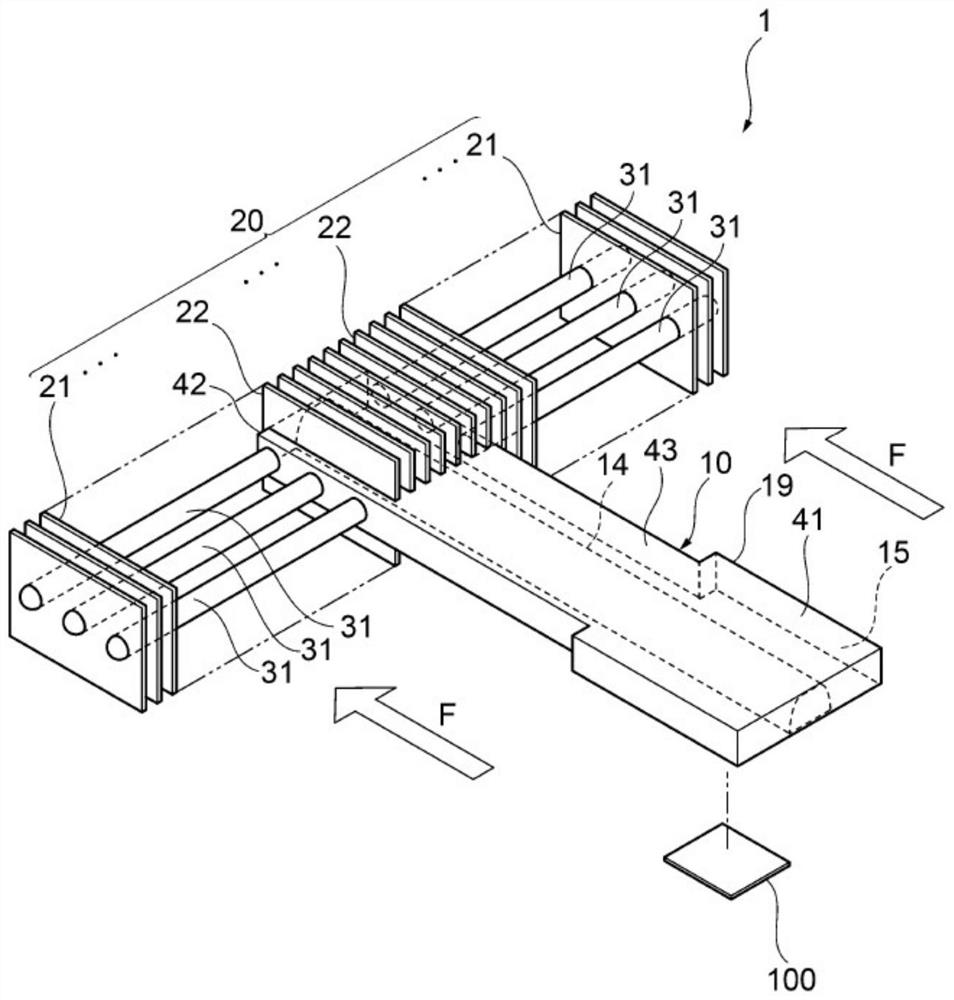
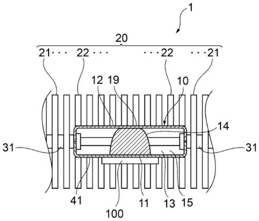
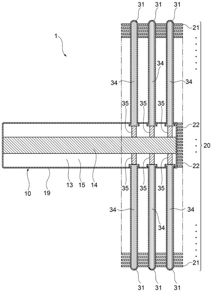
[0049] Hereinafter, a heat sink according to an embodiment example of the present invention will be described with reference to the drawings. figure 1 It is a schematic perspective view explaining the heat sink concerning the Example of this invention. figure 2 It is a schematic sectional view explaining the heat sink concerning the Example of this invention. image 3 It is a schematic explanatory drawing which shows the connection part of the heat-transfer member and a pipe body of the radiator concerning the Example of this invention. Figure 4 It is a schematic perspective view explaining the heat sink concerning the 2nd Embodiment of this invention. Figure 5 is a schematic plan view illustrating a heat sink according to a second embodiment of the present invention. Figure 6 is a schematic front view illustrating a heat sink according to a second embodiment of the present invention. Figure 7 is a schematic perspective view illustrating a heat sink according to a thir...


PUM


Abstract

The present invention provides a heat sink that can uniformize the heat of the heat receiving part and increase the volume of the heat receiving part, and prevent the thermal resistance of the heat receiving part from increasing even if the calorific value of the heat generating body increases, thereby affecting the cooling effect. Object exerts excellent cooling properties. The radiator includes: a heat transfer component having a heat receiving portion thermally connected to the heating element; a pipe body connected to the heat insulation portion or heat dissipation portion of the heat transfer member; a cooling fin group thermally connected to the pipe body, and A plurality of cooling fins are arranged; the heat transfer member has an integrated internal space, which connects the heat receiving part to the connection part connected with the pipe body, and is sealed with working fluid, and the heat transfer member The inner space of the pipe communicates with the inner space of the pipe body.

Description

technical field [0001] The present invention relates to a heat sink for cooling electric / electronic parts and the like, and particularly relates to a heat sink which can be installed in a narrow space. Background technique [0002] With the multifunctionalization of electronic equipment, heating elements such as electronic components are mounted at high density inside the electronic equipment. A fan heater can be used as a method of cooling a heat generating body such as an electronic component. As the heat sink, a heat sink including a tubular heat pipe (heat pipe type heat sink) is generally used. [0003] As a heat pipe type heat sink, for example, there is a heat pipe type heat sink provided with a plurality of flat fins protruding from the outer peripheral surface of a plurality of tubular heat pipes provided (Patent Document 1). The heat sink of Patent Document 1 is a heat sink configured to transfer heat from a heat generating body to fins through a plurality of tub...

Claims


Application Information

Patent Timeline
Patent Type & Authority Patents(China)
IPC IPC(8): H05K7/20H01L23/427F28D15/04F28F1/26
CPCF28D15/0266F28D15/04F28F1/26H01L23/427H05K7/20336H01L23/3672
Inventor 川田贤也佐佐木泰海渡边阳介
Owner FURUKAWA ELECTRIC CO LTD
Why Eureka
Try Eureka