Thermal superconducting fin radiator and electrical equipment chassis

A thermal superconducting, finned technology, applied in electrical equipment structural parts, electrical components, cooling/ventilation/heating renovation, etc., can solve the problem of inability to meet the heat dissipation requirements of high heat flux density and high power modules, poor heat dissipation capacity, volume Large and other problems, to achieve the effect of good work adaptability, guaranteed heat dissipation capacity, and small size

Active Publication Date: 2020-02-07
ZHEJIANG JIAXI TECH CO LTD
View PDF8 Cites 0 Cited by
  • Summary
  • Abstract
  • Description
  • Claims
  • Application Information

AI Technical Summary

Problems solved by technology

[0006] In view of the above-mentioned shortcomings of the prior art, the object of the present invention is to provide a thermal superconducting finned radiator and an electrical equipment chassis, which are used to solve the problem of large volume and heavy weight of the aluminum profile radiator in the prior art. , Poor heat dissipation, unable to meet the heat dissipation requirements of high heat flux density and high power modules

Method used


Image

  • Thermal superconducting fin radiator and electrical equipment chassis
  • Thermal superconducting fin radiator and electrical equipment chassis
  • Thermal superconducting fin radiator and electrical equipment chassis

Examples


Embodiment 1

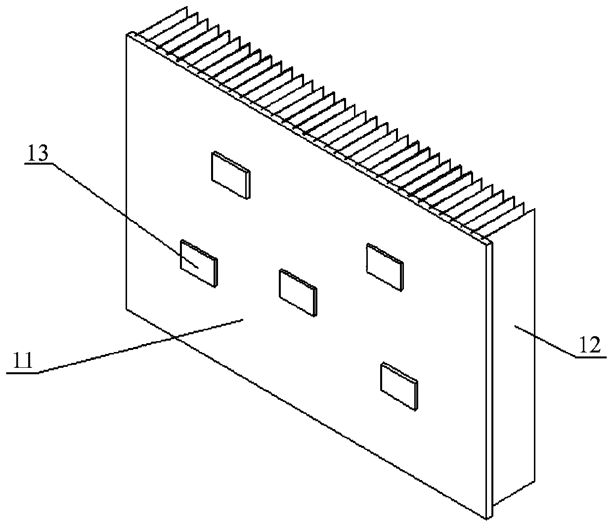
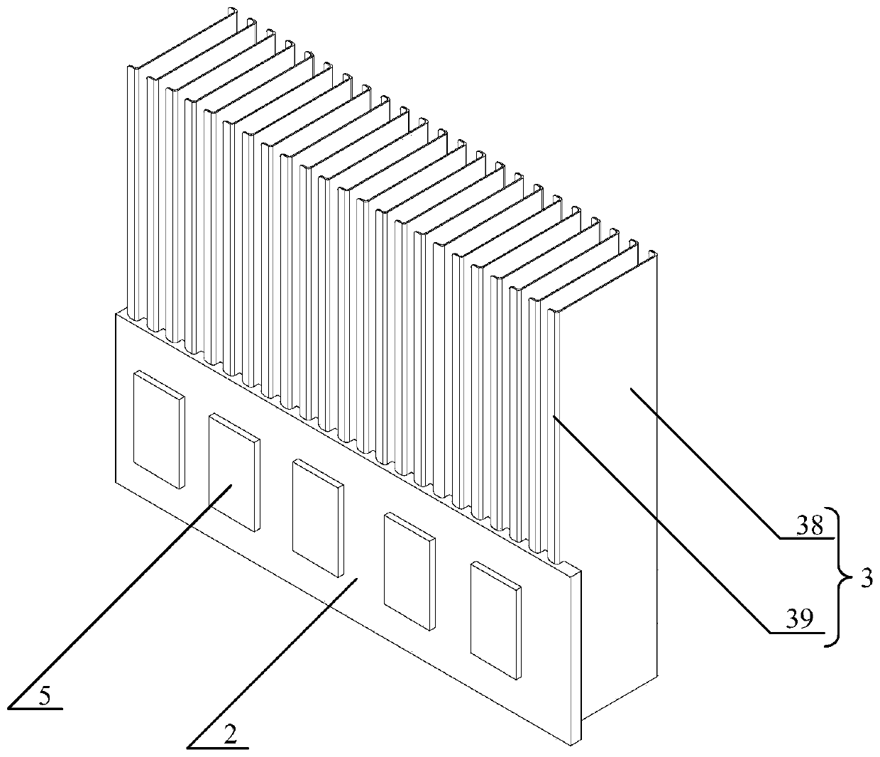
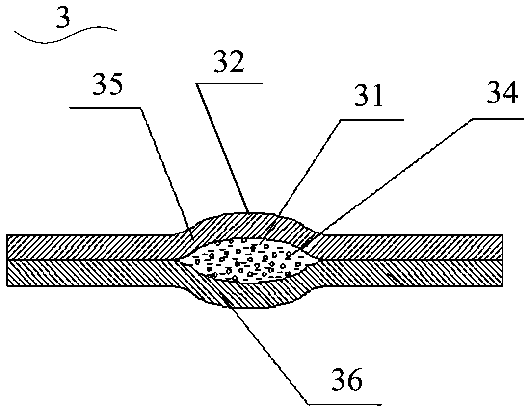
[0057] see Figures 2 to 6 , the present invention provides a thermal superconducting finned radiator, said thermal superconducting finned radiator comprising: radiator substrate 2; several thermal superconducting fins 3, said thermal superconducting fins 3 is inserted on the surface of the heat sink substrate 2; the thermal superconducting heat dissipation fin 3 is a composite plate structure, and a thermal superconducting circuit 31 of a specific shape is formed inside the thermal superconducting heat dissipation fin 3. The thermal superconducting pipeline 31 is a closed pipeline, and the thermal superconducting pipeline 31 is filled with a heat transfer working medium 34; the thermal superconducting fin 3 is a U-shaped plate structure, and the U-shaped plate structure includes Flat-shaped main body 38 and the bent side 39 compared with the flat-shaped main body 38; the projected area of ​​several thermal superconducting cooling fins 3 in the plane where the heat sink substr...

Embodiment 2

[0069] see Figure 7 , the present invention also provides a thermal superconducting fin radiator, the structure of the thermal superconducting fin radiator described in this embodiment is the same as the structure of the thermal superconducting fin radiator described in Embodiment 1 Roughly the same, the difference between the two is: compared with the thermal superconducting fin radiator described in Embodiment 1, the thermal superconducting fin radiator in this embodiment has added a reinforcing buckle 4, so The reinforcement buckle 4 is at least located on one side of the thermal superconducting fins 3, and extends along the arrangement direction of the thermal superconducting fins 3, and is connected with each thermal superconducting fin 3 The sides are fixedly connected. in, Figure 7 Among them, the number of the reinforcing buckles 4 is five, and three of the reinforcing buckles 4 are located on the side of the thermal superconducting heat dissipation fin 3 away from...

Embodiment 3

[0071]The present invention also provides an electrical equipment case, which includes: a main body of the case, the side or back of the main body of the case is provided with an opening communicating with the inside and outside; A finned heat sink, the thermal superconducting finned heat sink is fixed on the side of the chassis body where the opening is provided, and the heat sink substrate completely covers the opening; a power device, the power device is located The main body of the case is fixed on the surface of the radiator substrate away from the thermal superconducting fins.

[0072] To sum up, the present invention provides a thermal superconducting finned heat sink and an electrical equipment chassis. The thermal superconducting finned heat sink includes: a radiator substrate; several thermal superconducting fins inserted on the surface of the heat sink substrate; the thermal superconducting heat dissipation fin is a composite plate structure, and a thermal supercond...


PUM


Abstract

The invention discloses a heat superconducting fin type radiator and electrical device case, the heat superconducting fin type radiator comprises a radiator baseplate, a plurality of superconducting radiating fins which is arranged on the surface of the radiator baseplate; the superconducting radiating fin is composite plate structure, a particular shape of heat superconducting line is disposed in the heat superconducting radiating fin. The heat superconducting line is closed line and is stuffed with heat transferring media; the heat superconducting radiating fin is U style plate structure which comprise a flat plate body and a bending side compared to the flat plate body bending; the projection area of a plurality of heat superconducting radiating fins in the plane of the radiator baseplate is larger than that of the radiator basepalte. The projection area of a plurality of the heating superconducting radiating fins in the plane of the radiator baseplate is larger than that of the radiator baseplate; the weight of the radiator is decreased greatly under the precondition of ensuring the heat radiating capability.

Description

technical field [0001] The invention relates to a radiator for heat dissipation of high-power electronic devices, in particular to a thermal superconducting fin radiator and an electrical equipment case. Background technique [0002] With the rapid development of power electronics technology, the requirements for modularization, integration, lightweight, low cost and high reliability are getting higher and higher. Therefore, in solar inverters, uninterruptible power supplies (UPS), charging piles, power MosFET (metal oxide semiconductor field effect transistor), Diode (diode), IGBT ( Insulated Gate Bipolar Transistors) and other power devices. As the integration of these power components is getting higher and higher, the power density is also increasing, and the heat generated by themselves during work is also increasing. If the heat generated by the power devices cannot be dissipated in time and quickly, it will lead to power failure. The temperature of the chip in the de...

Claims


Application Information

Patent Timeline
Patent Type & Authority Patents(China)
IPC IPC(8): H05K7/20
CPCH05K7/20409
Inventor 仝爱星斯奕超罗启洪
Owner ZHEJIANG JIAXI TECH CO LTD
Why Eureka
Try Eureka