Reflowable Circuit Protection Device

a circuit protection device and surface mount technology, applied in the direction of non-electric welding apparatus, manufacturing tools, solventing apparatus, etc., can solve the problems of sensing element premature opening, existing thermal fuses cannot be mounted to circuit panels, and care must be taken to prevent thermal fuses from reaching

Active Publication Date: 2015-11-05
LITTELFUSE FRANCE SAS +1
View PDF9 Cites 15 Cited by
  • Summary
  • Abstract
  • Description
  • Claims
  • Application Information

AI Technical Summary

Problems solved by technology

One disadvantage of some existing thermal fuses is that during installation of the thermal fuse, care must be taken to prevent the thermal fuse from reaching the temperature at which the sensing elem

Method used


Image

  • Reflowable Circuit Protection Device
  • Reflowable Circuit Protection Device
  • Reflowable Circuit Protection Device

Examples


Embodiment Construction

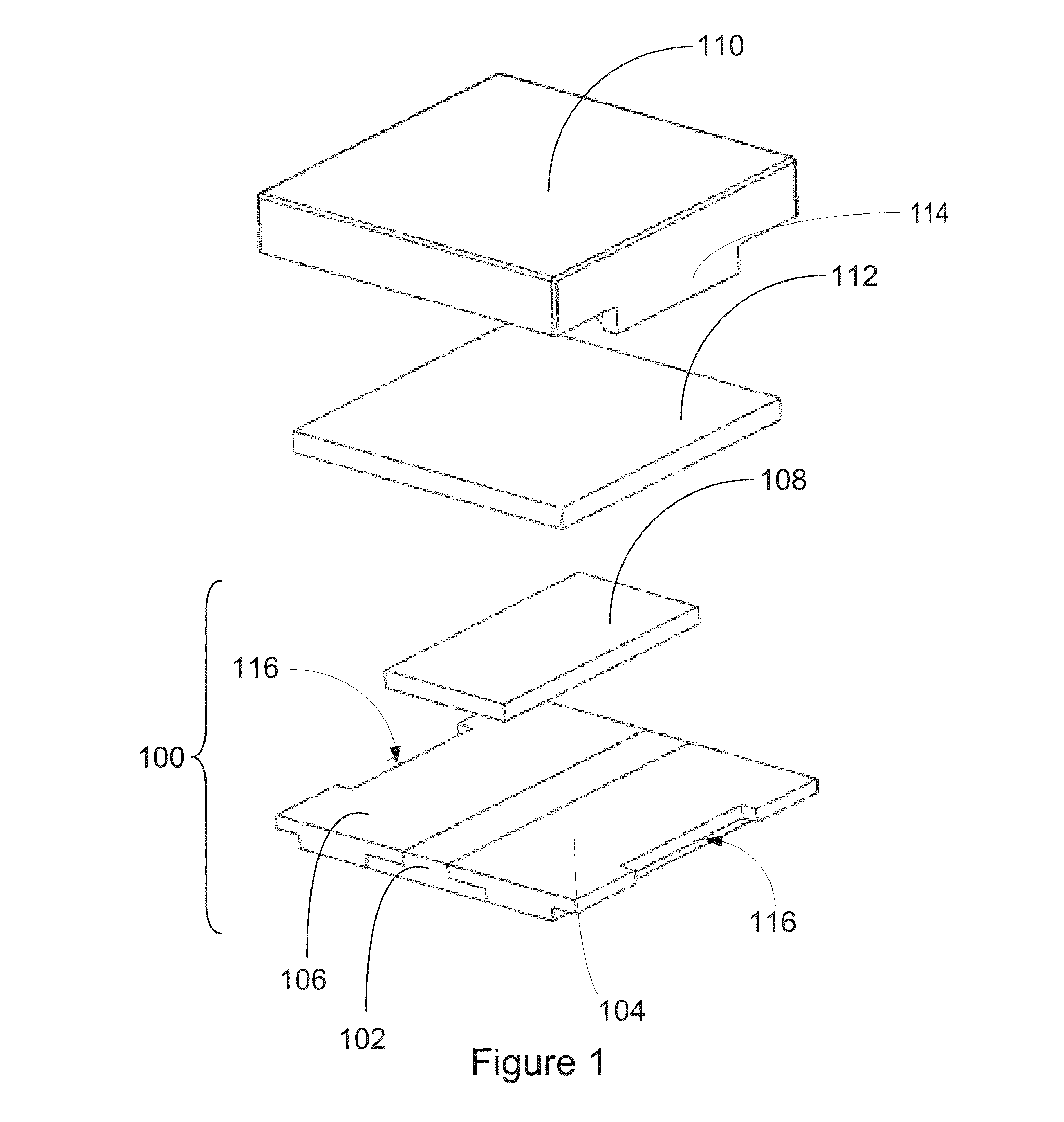
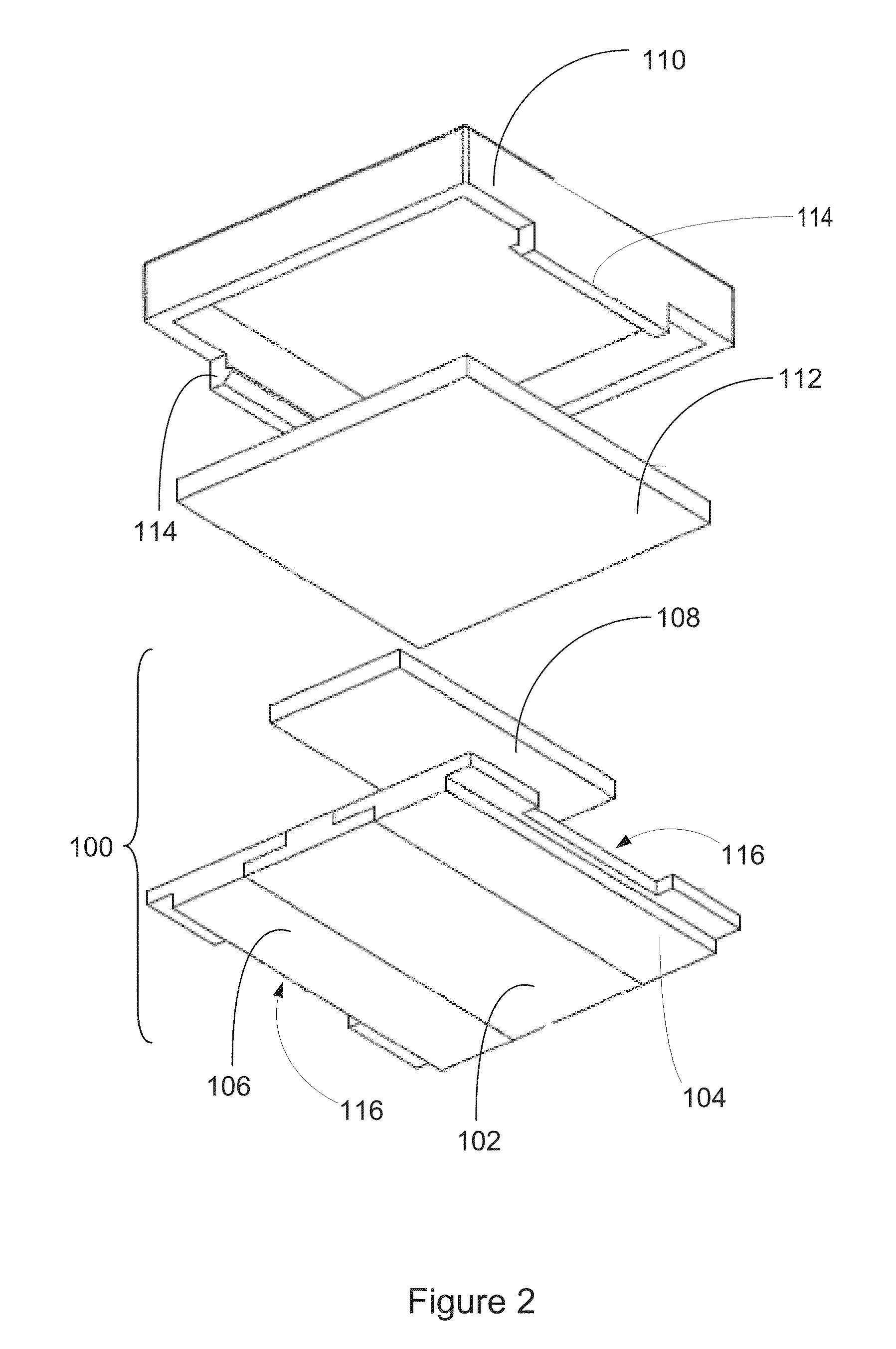
[0042]FIGS. 1 and 2 show exploded views of a reflowable circuit protection device. The device includes a base assembly 100, which includes a dielectric 102 formed between two electrodes 104, 106. The device connects to an external circuit through the electrodes 104, 106. At least a portion of the lower surface of each electrode 104, 106 is mounted on a printed circuit board when the device is installed. The width (w) of the portion of the dielectric 102 between the upper surfaces of each of the electrodes 104, 106 may be between about 0.5 mm and about 1.0 mm.

[0043]The base assembly 100 also includes a low melting point metal 108, such as a solder link, is formed above at least a portion of the dielectric 102 and electrodes 104, 106 to form a conductive bridge between the electrodes 104, 106. In one embodiment, the low melting point metal 108 may have a height of about 0.25 mm, a width of about 2.0 mm, and a length of about 5.0 mm or less. The low melting point metal has a melting po...


PUM

PropertyMeasurementUnit
Temperatureaaaaaaaaaa
Forceaaaaaaaaaa
Coloraaaaaaaaaa

Abstract

A circuit protection device includes a base assembly, a spring on top of the base, a conductive terminal that fits over the base and spring, and a cap that first over the base, spring and terminal. The base includes latches on the front side of the base. The conductive terminal includes a first end on the front side of the base and a second end on a rear side of the base that is opposite to the front side. The cap includes a first protrusion extending downward from the cap above one of the latches and a second protrusion extending downward from the cap above the other latch. The circuit protection device also includes a means for activating the circuit protection device after reflow in response to a force applied to the cap in a first direction defined from a top of the cap towards the base.

Description

BACKGROUND[0001]1. Field of the Invention p The present invention relates generally to electronic protection circuitry. More, specifically, the present invention relates to a reflowable surface mount circuit protection device.[0002]2. Background of the Invention[0003]Protection circuits are often times utilized in electronic circuits to isolate failed circuits from other circuits. For example, the protection circuit may be utilized to prevent electrical or thermal fault condition in electrical circuits, such as in lithium-ion battery packs. Protection circuits may also be utilized to guard against more serious problems, such as a fire caused by a power supply circuit failure.[0004]One type of protection circuit is a thermal fuse. A thermal fuse functions similar to that of a typical glass fuse. That is, under normal operating conditions the fuse behaves like a short circuit and during a fault condition the fuse behaves like an open circuit. Thermal fuses transition between these two...

Claims


Application Information

Patent Timeline
IPC IPC(8): H01H37/70H01H37/04B23K1/00H01H11/00B23K31/02H01H37/76H01H37/32
CPCH01H37/70H01H37/761H01H37/04H01H37/32H01H11/00H01H2229/00B23K1/0016H01H2037/762H01H2235/01H01H2239/072B23K31/02H01H37/08H01H2037/046
Inventor MATTHIESEN, MARTYN A.VRANICAR, ANTHONYCHEN, JIANHUAHOU, DAPENG
Owner LITTELFUSE FRANCE SAS
Why Eureka
Try Eureka