Feeding fence section

Active Publication Date: 2015-11-12
COW WELFARE
View PDF33 Cites 5 Cited by
  • Summary
  • Abstract
  • Description
  • Claims
  • Application Information

AI Technical Summary

Benefits of technology

[0025]Arranging the flexible mounting means at both ends of the feeding fence section is adv

Problems solved by technology

It has been found that cows may apply a force of more than 800 Newton with their shoulders and forepart against the feeding fence

Method used


Image

  • Feeding fence section
  • Feeding fence section
  • Feeding fence section

Examples


Embodiment Construction

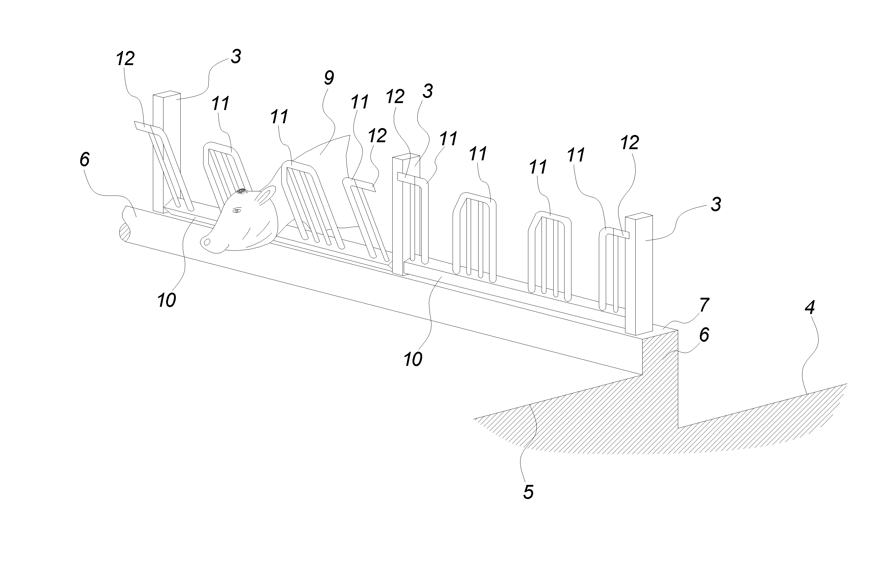
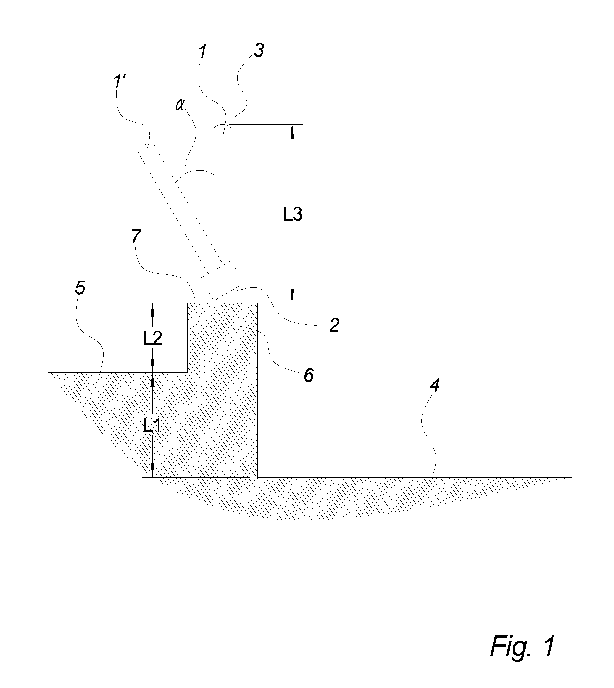
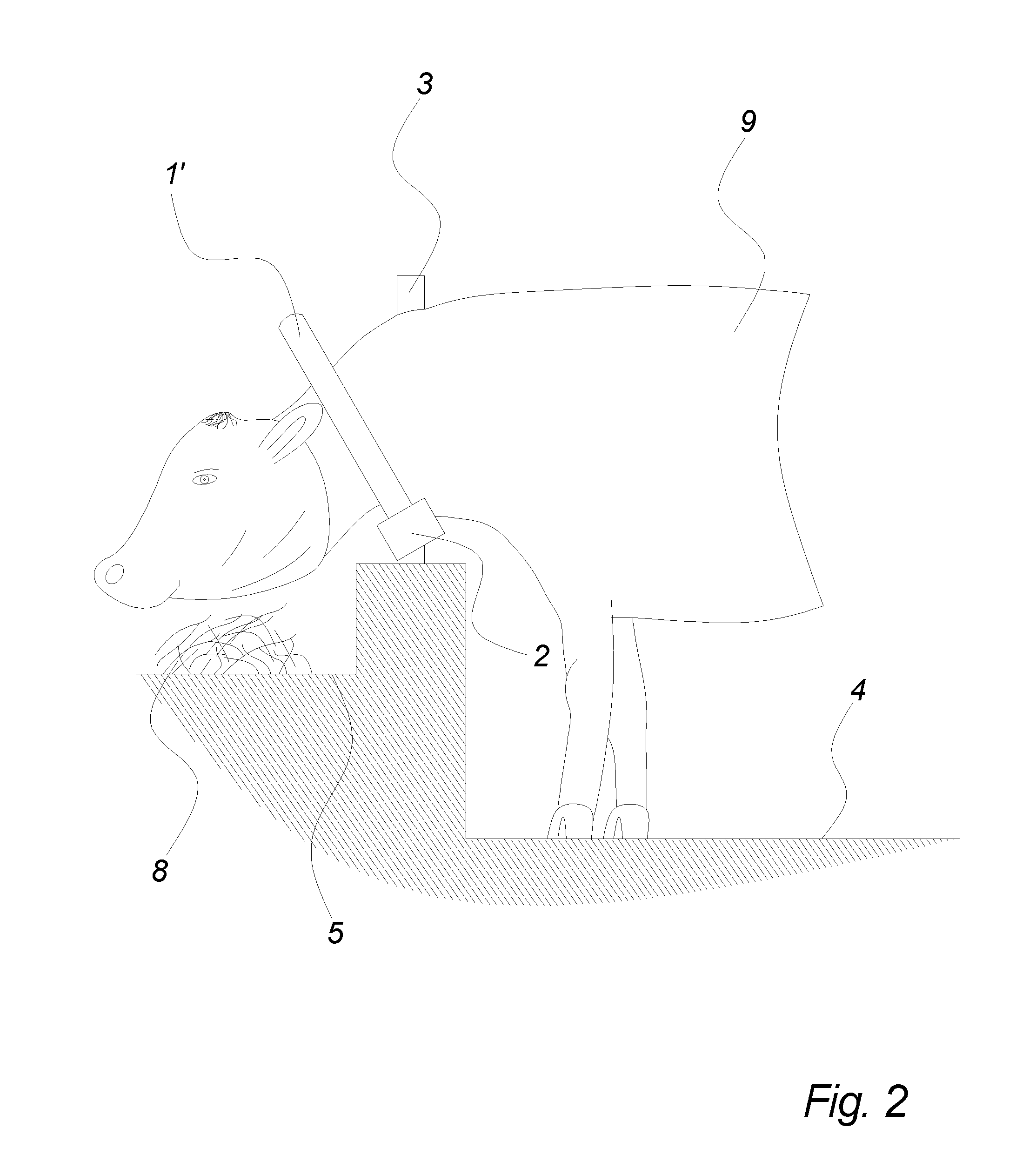
[0034]The cross-section in FIGS. 1 and 2 show a feeding stable arrangement comprising a feeding area 4 for holding the animals, such as cows 9, and a feed-holding part in the form of a feeding table 5 for holding the feed 8 for the animals. The feeding area 4 and the feed-holding part 5 are separated by an edge part 6 on the top 7 of which is arranged a feeding fence formed from a number of feeding fence sections 1 supported by means of flexible mounting parts 2 on intermediate upright stationary posts 3. The feeding fence section 1 is biased by the flexible mounting parts 2 to a starting position, which in the examples shown in the drawing is vertical, but which in alternative embodiments may be tilted 5-10° towards the feed-holding part 5. When the animal 9 pushes against the feeding fence section 1 it will tilt towards the feed-holding part 5 to a tilted position of the feeding fence section 1′ with a maximum angular deviation a from vertical of 30°, the vertical position being t...


PUM


Abstract

A feeding fence section (1, 1′) suitable for separating a feeding area (4) for animals and a feed-holding part (5) is disclosed, where the feeding fence section (1, 1′) is provided with flexible mounting means (2), which allows the fence section (1, 1′) to be angularly displaced by said animals from a starting position (1) towards a tilted position (1′) about a substantially horizontal, longitudinal axis, wherein the mounting means (2) are biasing the fence section from said tilted position (1′) towards the starting position (1).

Description

[0001]The present invention relates to a feeding fence section for a feeding fence separating a feeding area for animals, in particular for cows, and a feed-holding part, such as a feeding table.BACKGROUND[0002]Feeding fences, also known as feeding barriers and in particular embodiments as head gates, have been known for centuries for separating the area where the animals are enclosed and the area where the feed for the animals are provided, commonly known as the feeding table. The feeding fence prevents the animals from soiling the feed and may furthermore be provided with head openings for the individual animal to allow the animals to eat undisturbed by the neighbouring animals.[0003]In case some of the feed is placed on the feeding table outside the reach of the animals, they may push so strongly against the feeding fence that they may inflict injuries on themselves and care should be taken when feeding the animals that all feed is placed within reach of the animals, and the feed...

Claims


Application Information

Patent Timeline
IPC IPC(8): E06B11/02A01K29/00E04H17/00A01K5/01
CPCE06B11/027E04H17/00A01K29/00A01K5/01A01K1/10A01K1/105
Inventor WOLLESEN, TOMMY
Owner COW WELFARE
Why Eureka
Try Eureka