Low-loss persistent current switch with heat transfer arrangement

a persistent current switch and low-loss technology, applied in the direction of superconducting magnets/coils, instruments, magnetic bodies, etc., can solve the problems of high cost, large number of resistive persistent current switches, and energy dissipation,

Active Publication Date: 2015-11-12
KONINKLJIJKE PHILIPS NV
View PDF5 Cites 19 Cited by
  • Summary
  • Abstract
  • Description
  • Claims
  • Application Information

AI Technical Summary

Benefits of technology

[0003]Superconducting magnets are used in a variety of contexts, including nuclear magnetic resonance (NMR) analysis, and magnetic resonance imaging (MRI). To realize superconductivity, a magnet is maintained in a cryogenic environment at a temperature near absolute zero. Typically, the magnet includes one or more electrically conductive coils which are disposed in a cryostat and are cooled by a cryogenic fluid such as liquid helium.

Problems solved by technology

This typically dissipates energy in the persistent current switch.
Refrigeration systems are typically inefficient at removing heat in very low temperature (cryogenic) environments.
As a result, this typically requires very large, expensive, resistive persistent current switches to be employed, or costly cryogens are allowed to be boiled off which are replaced after the magnet has been charged.

Method used


Image

  • Low-loss persistent current switch with heat transfer arrangement
  • Low-loss persistent current switch with heat transfer arrangement
  • Low-loss persistent current switch with heat transfer arrangement

Examples


Embodiment Construction

[0033]The present invention will now be described more fully hereinafter with reference to the accompanying drawings, in which embodiments of the present invention are shown. The present invention may, however, be embodied in different forms and should not be construed as limited to the embodiments set forth herein. Rather, these embodiments are provided as teaching examples of the invention. Within the present disclosure and claims, when something is said to have approximately a certain value, then it means that it is within 10% of that value, and when something is said to have about a certain value, then it means that it is within 25% of that value.

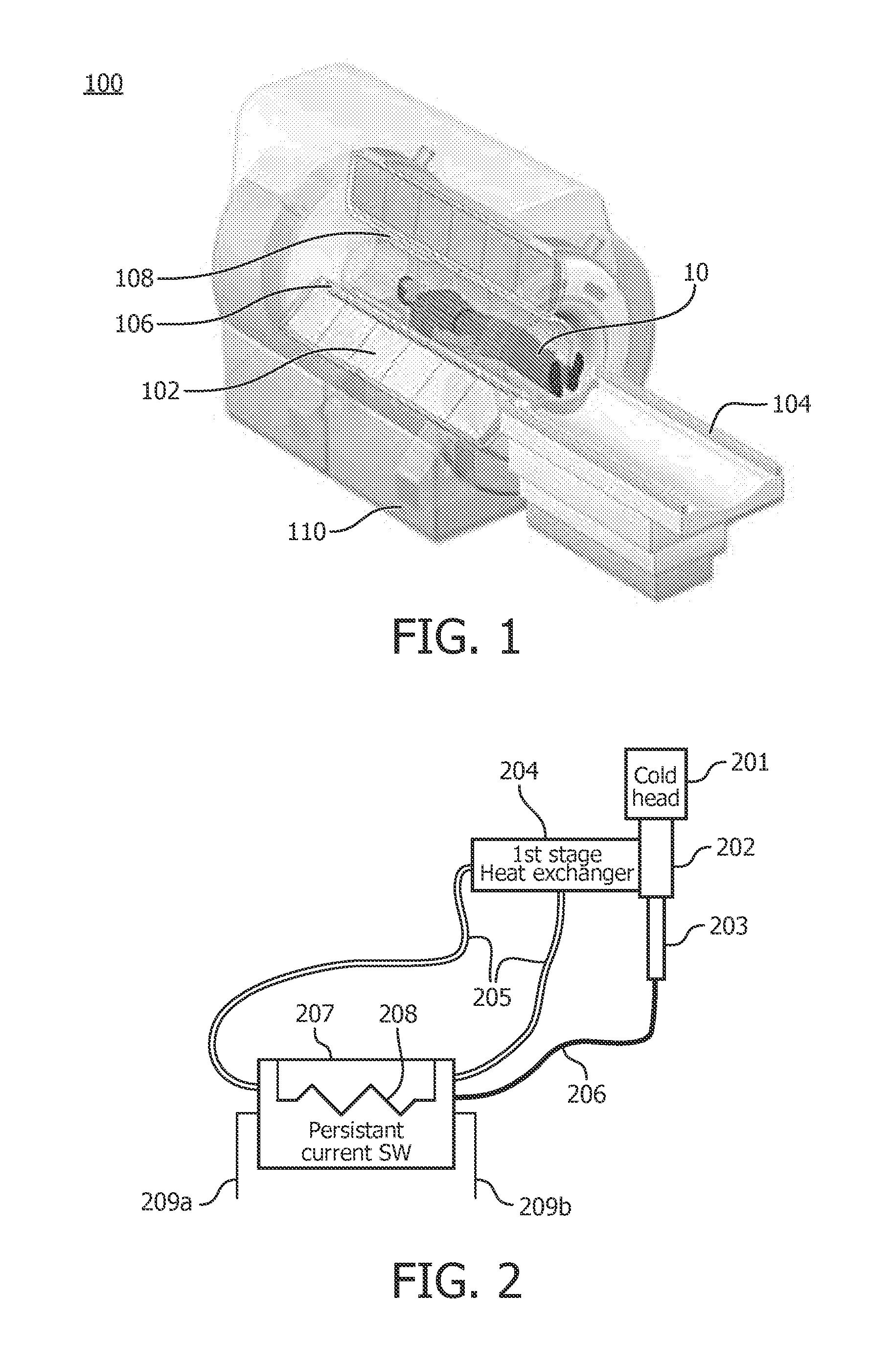
[0034]FIG. 1 illustrates an exemplary embodiment of a magnetic resonance imaging (MRI) apparatus 100. MRI apparatus 100 includes a magnet 102; a patient table 104 configured to hold a patient 10; gradient coils 106 configured to at least partially surround at least a portion of patient 10 for which MRI apparatus 100 generates an image; ...


PUM


Abstract

An apparatus including a persistent current switch of a superconducting material which is electrically superconducting at a superconducting temperature and electrically resistive at a resistive mode temperature which is greater than the superconducting temperature. The apparatus further includes a first heat exchange element; a convective heat dissipation loop thermally coupling the persistent current switch to the first heat exchange element; a second heat exchange element spaced apart from the first heat exchange element; and a thermally conductive link thermally coupling the persistent current switch to the second heat exchange element. The first heat exchange element is disposed above the persistent current switch. The thermally conductive link may have a greater thermal conductivity at the superconducting temperature than at a second temperature which is greater than the superconducting temperature.

Description

CROSS REFERENCE TO PRIOR APPLICATION[0001]This application claims the benefit of U.S. Provisional Patent Application No. 61 / 737,939, filed Dec. 17, 2013 which is hereby incorporated by reference herein.TECHNICAL FIELD[0002]The present invention generally pertains to a low-loss persistent current switch, and in particular, to a low-loss persistent current switch for use with a superconducting persistent magnet in a cryogenic environment.BACKGROUND AND SUMMARY[0003]Superconducting magnets are used in a variety of contexts, including nuclear magnetic resonance (NMR) analysis, and magnetic resonance imaging (MRI). To realize superconductivity, a magnet is maintained in a cryogenic environment at a temperature near absolute zero. Typically, the magnet includes one or more electrically conductive coils which are disposed in a cryostat and are cooled by a cryogenic fluid such as liquid helium.[0004]Many superconducting magnets operate in “persistent mode.” In persistent mode, one or more s...

Claims


Application Information

Patent Timeline
Patent Type & Authority Applications(United States)
IPC IPC(8): G01R33/38G01R33/3815
CPCG01R33/3815G01R33/3804H01F6/04H01F6/006
Inventor JONAS, PHILIP ALEXANDERAKHMETOV, ALEXANDERACKERMANN, ROBERT ADOLPHMENTEUR, PHILIPPE ABELPFLEIDERER, GLEN GEORGEVOSS, MATTHEW
Owner KONINKLJIJKE PHILIPS NV
Why Eureka
Try Eureka