Pelvic Implant Needle System and Method

a technology of pelvis and needles, applied in the field of surgical methods and equipment, can solve the problems of affecting the quality of life of patients, and affecting the quality of life of patients

Active Publication Date: 2015-11-19
BOSTON SCI SCIMED INC
View PDF9 Cites 4 Cited by
  • Summary
  • Abstract
  • Description
  • Claims
  • Application Information

AI Technical Summary

Benefits of technology

[0009]The present invention describes an implant or sling insertion needle or trocar system, device and method. While typical trocars can include a curved stainless steel needle to create a pathway for a supporting mesh sling, embodiments of the present needle device can include a solid or hollow needle shaft portion with a non-circular cross-section. The use of a non-circular form for the needle provides distinct functional advantages.
[0010]Namely, a needle device having a non-circular cross-section needle shaft can provide improved visual and tactile feedback pertaining to the orientation of the needle, better gripping control of the needle, and improved finger contact surfaces to reduce finger pressure and slippage.
[0011]Embodiments can include a needle device having a housing or grip element. The grip can be constructed of a rigid plastic material, suitably shaped for gripping by the physician's fingers. The grip element can include flats, curved portions, holes, a through-aperture or other constraining means by which it may be slidably attached to the needle. In certain embodiments, for instance, the through-aperture is shaped and sized to generally match the shape and size of the needle, e.g., non-circular cross-section. As such, the grip element can slide along a longitudinal length of the non-circular cross-section needle, while still restricting rotational movement about the needle shaft. A mechanism can be included with the element, e.g., button or actuator, to selectively stop sliding of the element along the needle when desired. The mechanism allows the physician to apply both axial and rotational loads on the needle.

Problems solved by technology

Pelvic disorders such as these can result from weakness or damage to normal pelvic support systems.
In its severest forms, vaginal vault prolapse can result in the distension of the vaginal apex outside of the vagina.
These procedures often involve lengthy surgical procedure times.

Method used


Image

  • Pelvic Implant Needle System and Method
  • Pelvic Implant Needle System and Method
  • Pelvic Implant Needle System and Method

Examples


Embodiment Construction

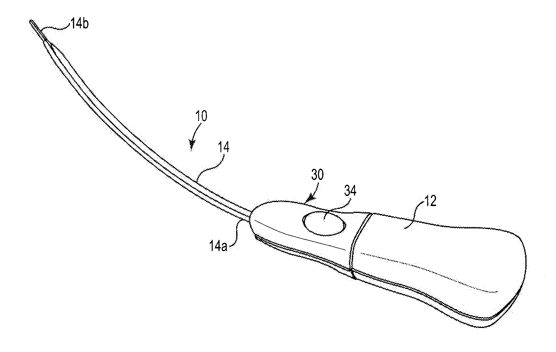
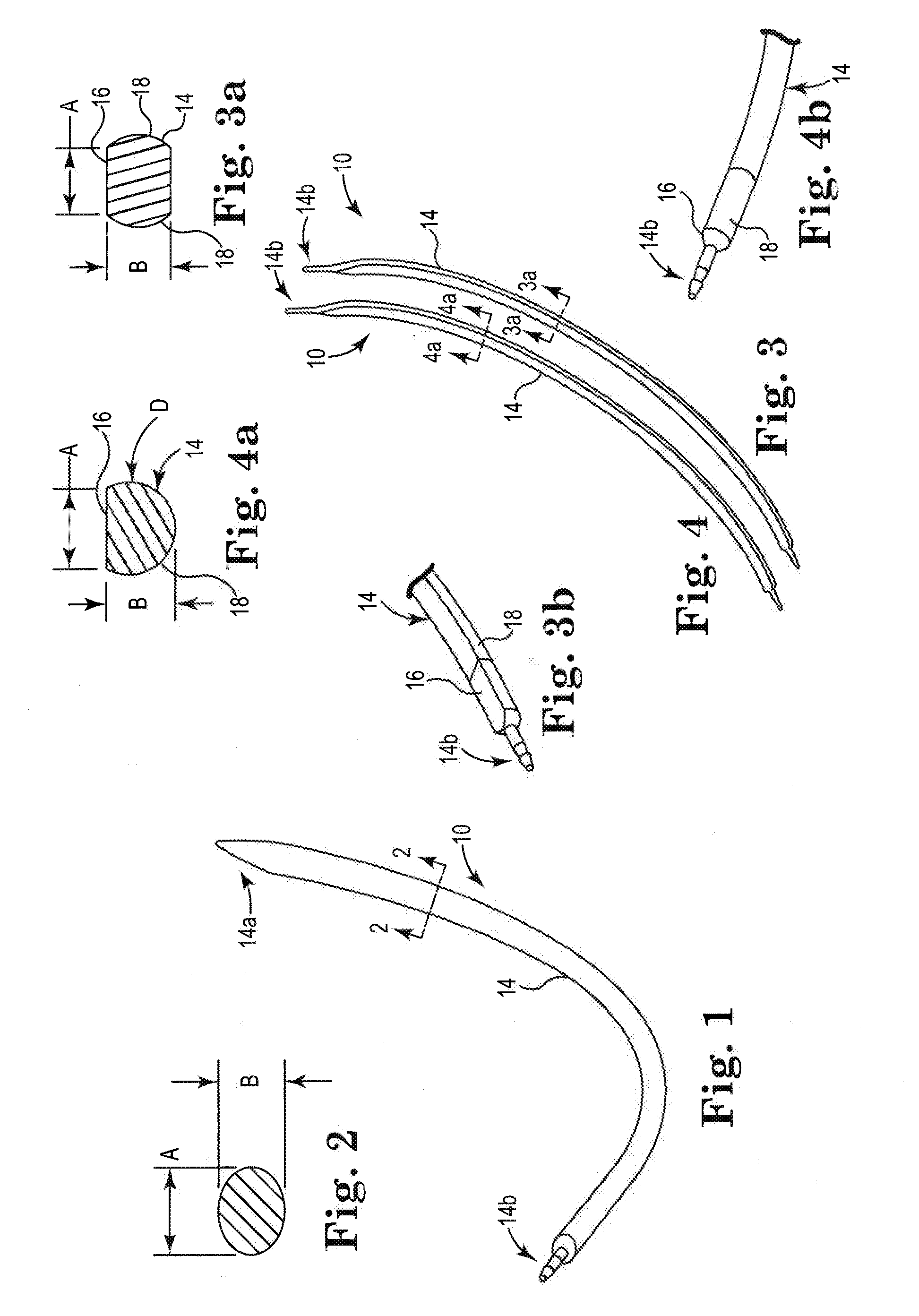
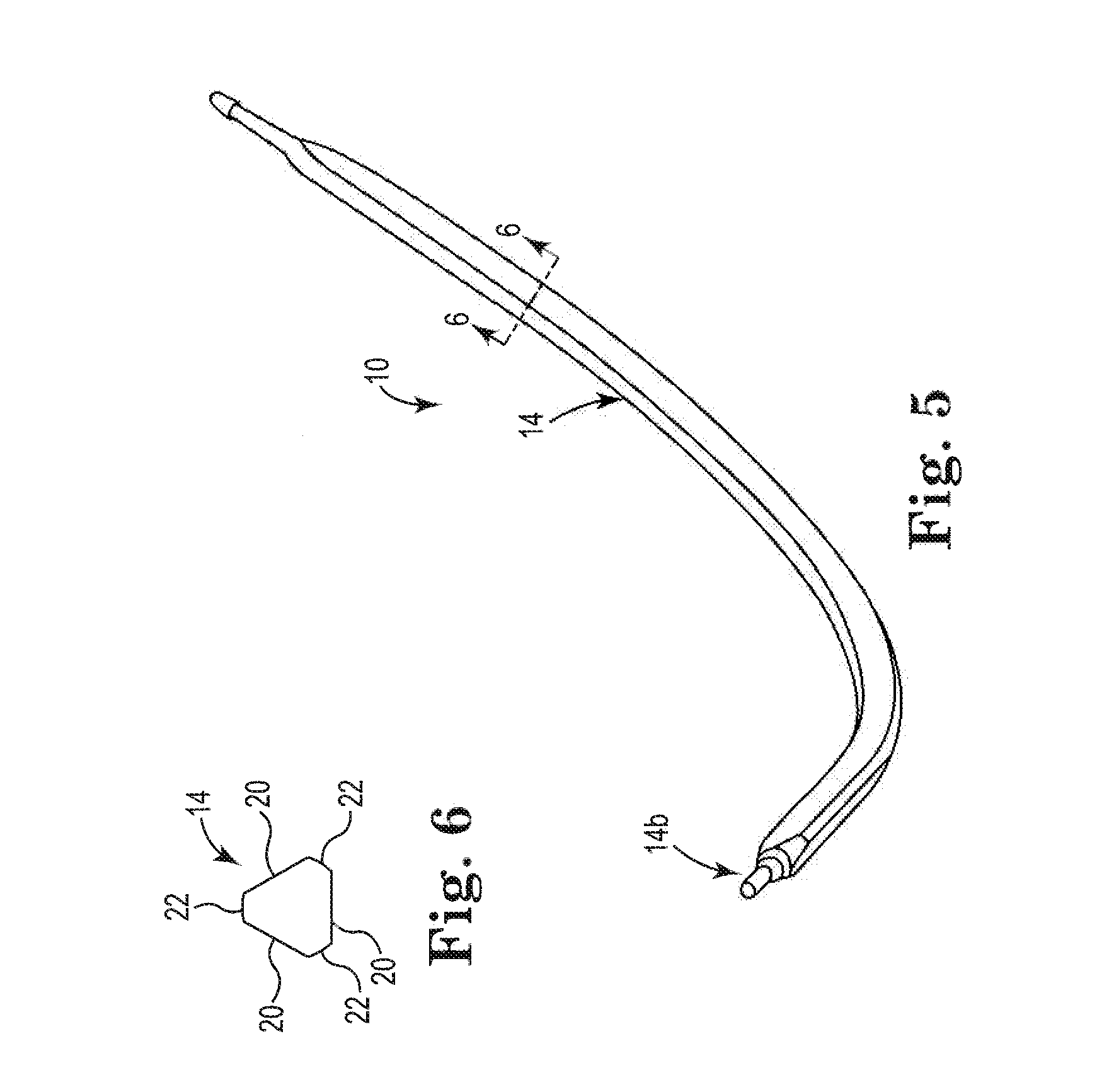
[0027]Referring generally to FIGS. 1-10, various embodiments of a trocar or needle device 10 are shown. The needle device 10 described and depicted herein can be employed in introducing or deploying implants used to treat pelvic conditions such as incontinence (various forms such as fecal incontinence, stress urinary incontinence, urge incontinence, mixed incontinence, etc.), vaginal prolapse (including various forms such as enterocele, cystocele, rectocele, apical or vault prolapse, uterine descent, etc.), and other conditions caused by muscle and ligament weakness. Implants utilized with the system can include a tissue support portion and one or more anchors, arms and the like, as disclosed herein.

[0028]The needle devices 10 can include a handle portion 12 and a needle portion 14. The needle portion 14 can be curved, straight, helical, and the like. The needle portion 14 can include a proximal portion 14a and a distal tip portion 14b. The proximal portion 14a can be operatively co...


PUM


Abstract

Various embodiments of a trocar or needle system for use in inserting and deploying pelvic implants are provided. The needle device can include a solid or hollow shaft portion with a non-circular cross-section. A grip element can be provided to slide along a length of the needle shaft to further facilitate handling.

Description

PRIORITY[0001]This Application is a Continuation Application of U.S. patent application Ser. No. 13 / 602,857, filed Sep. 4, 2012, which claims priority to and the benefit of U.S. Provisional Patent Application No. 61 / 530,380, filed Sep. 1, 2011; each of which is incorporated fully herein by reference.FIELD OF THE INVENTION[0002]The present invention relates generally to surgical methods and apparatus and, more specifically, to surgical trocar or needle devices used for introducing and deploying an implant or sling to treat incontinence or other pelvic disorders.BACKGROUND OF THE INVENTION[0003]Pelvic health for men and women is a medical area of increasing importance, at least in part due to an aging population. Examples of common pelvic ailments include incontinence (e.g., fecal and urinary), pelvic tissue prolapse (e.g., female vaginal prolapse), and conditions of the pelvic floor.[0004]Urinary incontinence can further be classified as including different types, such as stress urin...

Claims


Application Information

Patent Timeline
Patent Type & Authority Applications(United States)
IPC IPC(8): A61F2/00A61B17/06A61B17/34
CPCA61F2/0063A61B17/3476A61F2/0045A61F2002/0072A61B2017/00805A61B2017/0046A61B2017/0042A61B17/06109
Inventor ALLEN, JOHN J.MUJWID, JAMES R.GASTON, JOHANNES N.
Owner BOSTON SCI SCIMED INC
Why Eureka
Try Eureka