Ram accelerator system with endcap

Active Publication Date: 2015-11-19
HYPERSCI
View PDF13 Cites 21 Cited by
  • Summary
  • Abstract
  • Description
  • Claims
  • Application Information

AI Technical Summary

Problems solved by technology

The use of explosives results in additional safety and regulatory burdens which increase operational cost.
Typically these methods cycle from drill, blast, removal of material, ground support

Method used


Image

  • Ram accelerator system with endcap
  • Ram accelerator system with endcap
  • Ram accelerator system with endcap

Examples


Embodiment Construction

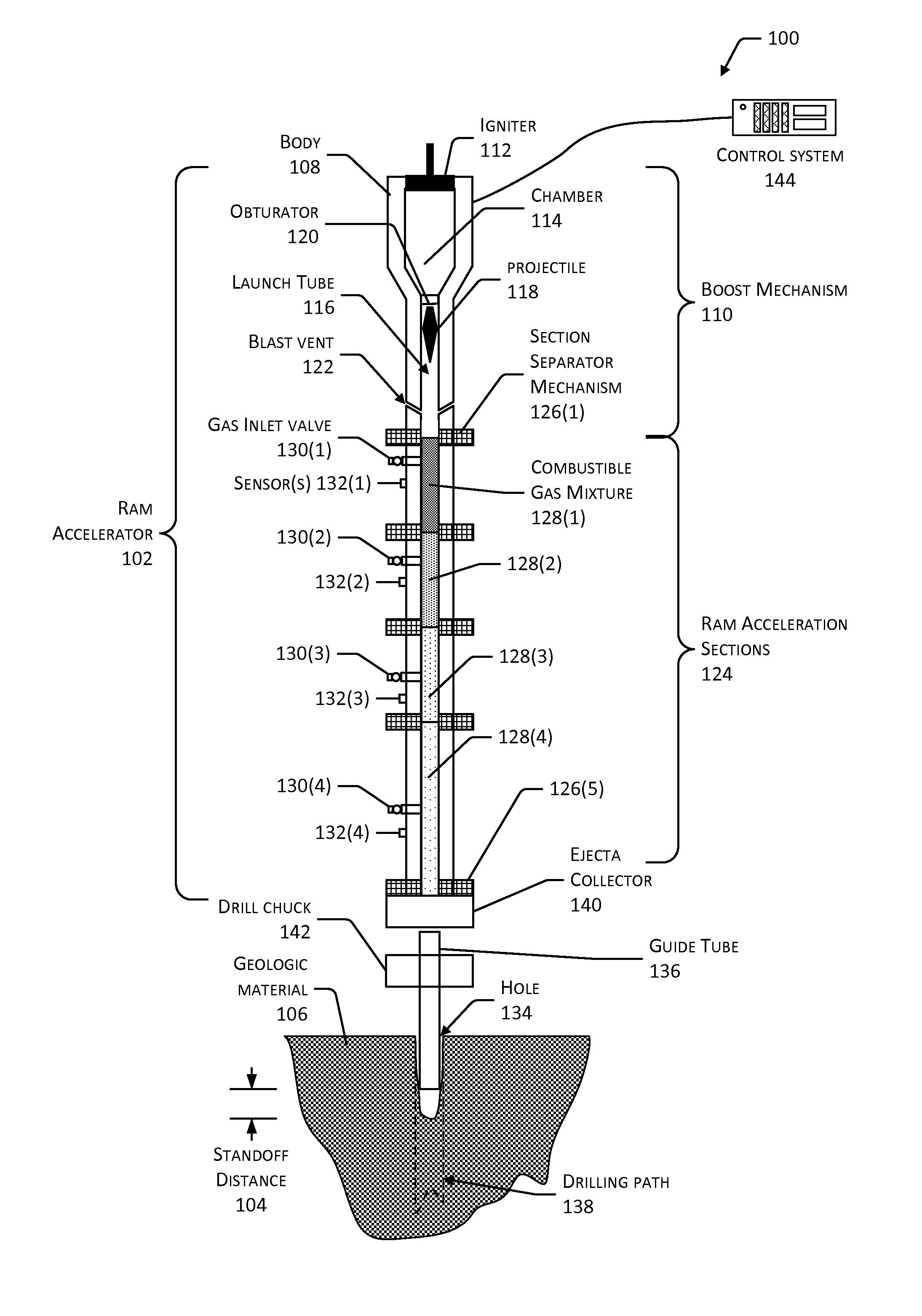
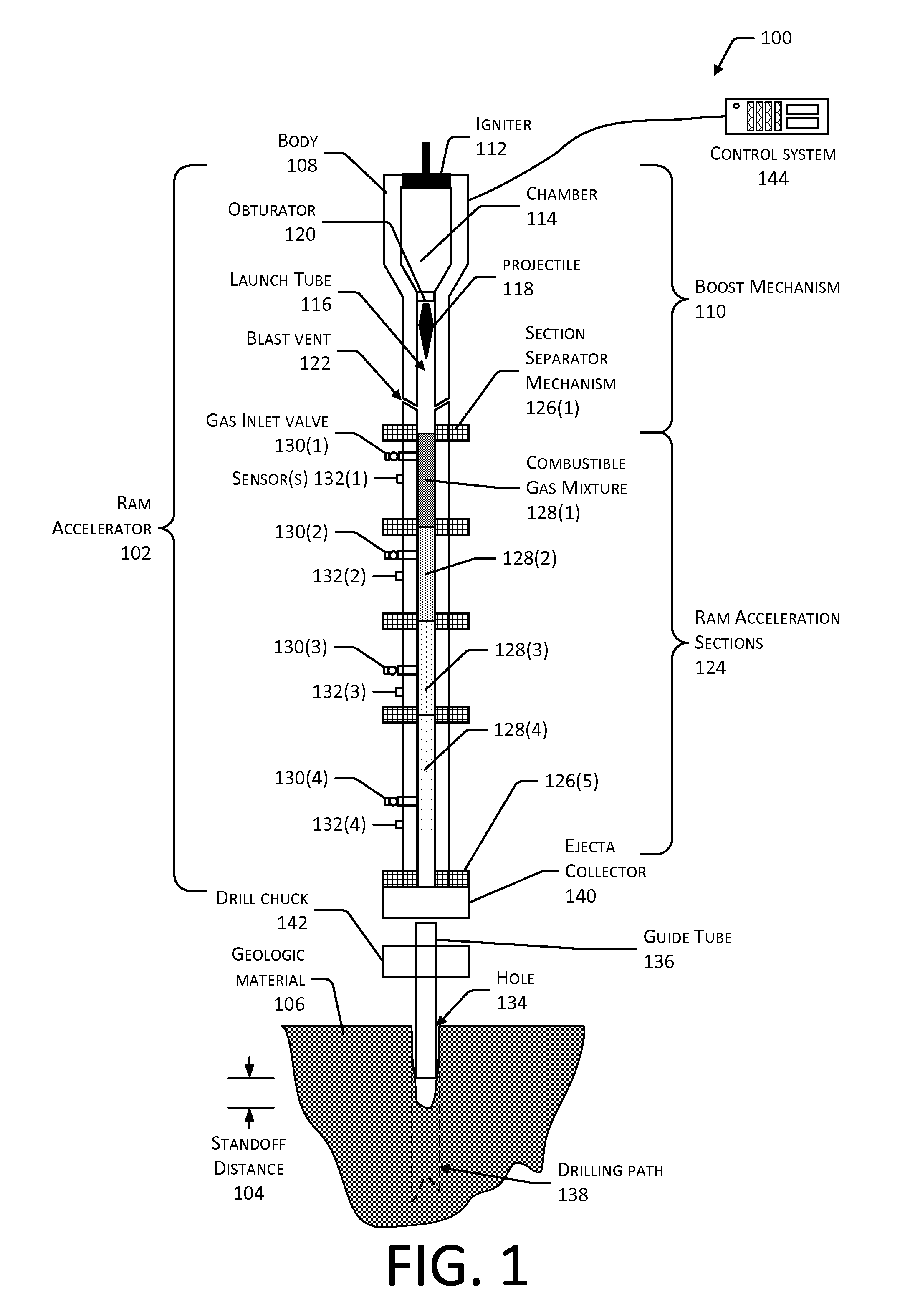
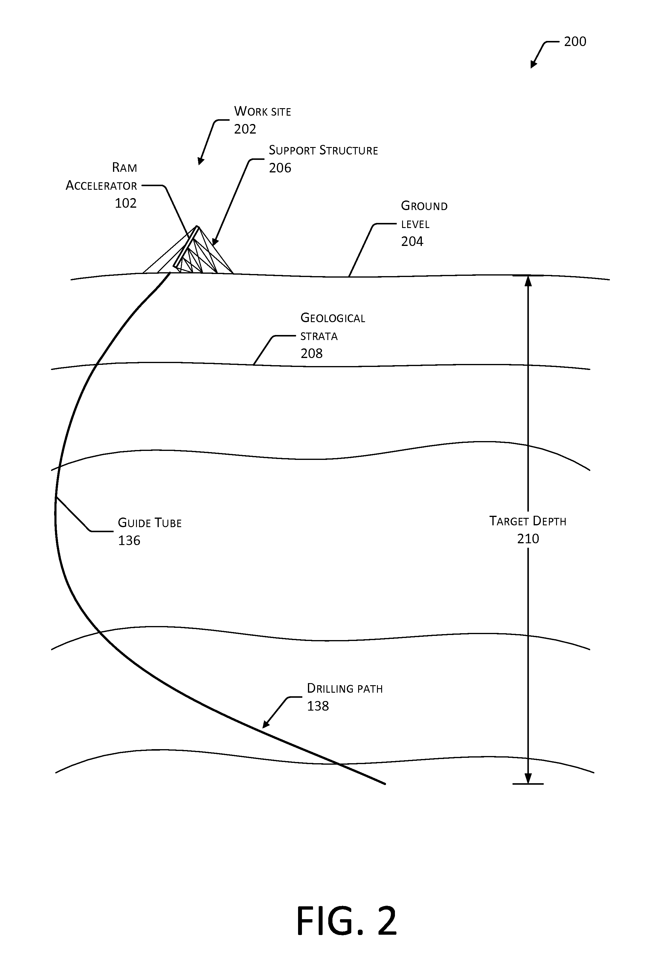
[0021]Conventional drilling and excavation techniques used for penetrating materials typically rely on mechanical bits used to cut or grind at a working face. These materials may include metals, ceramics, geologic materials, and so forth. Tool wear and breakage on the mechanical bits slows these operations, increasing costs. Furthermore, the rate of progress of cutting through material such as hard rock may be prohibitive. Drilling may be used in the establishment of water wells, oil wells, gas wells, underground pipelines, and so forth. Additionally, the environmental impact of conventional techniques may be significant. For example, conventional drilling may require a significant supply of water which may not be readily available in arid regions. As a result, resource extraction may be prohibitively expensive, time consuming, or both.

[0022]Described in this disclosure are systems and techniques for using a ram accelerator to eject one or more projectiles toward the working face of...


PUM


Abstract

One or more ram accelerator devices may be used to form one or more holes in geologic or other material. These holes may be used for drilling, tunnel boring, excavation, and so forth. The ram accelerator devices propel projectiles which are accelerated by combustion of one or more combustible gasses in a ram effect to reach velocities exceeding 500 meters per second. An endcap may be deployed within a tube of the ram accelerator device to prevent incursion of formation pressure products such as oil, water, mud, gas, and so forth into a guide tube of the ram accelerator. During operation the projectile penetrates the endcap and at least a portion thereof impact a working face. In some implementations a purge gas may be used to form a ullage between the endcap and the working face.

Description

PRIORITY[0001]This application claims priority to U.S. Provisional Patent Application Ser. No. 61 / 992,830 filed on May 13, 2014, titled “Ram Accelerator System With Endcap”, the contents of which are incorporated by reference into the present disclosure.BACKGROUND[0002]Traditional drilling and excavation methods utilize drills to form holes in one or more layers of material to be penetrated. Excavation, quarrying, and tunnel boring may also use explosives placed in the holes and detonated in order to break apart at least a portion of the material. The use of explosives results in additional safety and regulatory burdens which increase operational cost. Typically these methods cycle from drill, blast, removal of material, ground support and are relative slow (many minutes to hours to days per linear foot is typical depending on the cross-sectional area being moved) methods for removing material to form a desired excavation.BRIEF DESCRIPTION OF DRAWINGS[0003]Certain implementations an...

Claims


Application Information

Patent Timeline
IPC IPC(8): E21B7/00F41A1/04F41A1/02
CPCE21B7/007F41A1/04F41A1/02E21C37/04E21D9/106E21B7/00E21B10/26
Inventor RUSSELL, MARK C.
Owner HYPERSCI
Why Eureka
Try Eureka