
Method and apparatus for controlling focal vergence of optical content

a technology of optical content and control method, applied in the direction of optics, optical elements, instruments, etc., can solve the problem of problematic control of output content focal vergence “upstream” from the display itsel

Active Publication Date: 2015-11-19
WEST TEXAS TECH PARTNERS LLC
View PDF2 Cites 3 Cited by
  • Summary
  • Abstract
  • Description
  • Claims
  • Application Information

AI Technical Summary

Benefits of technology

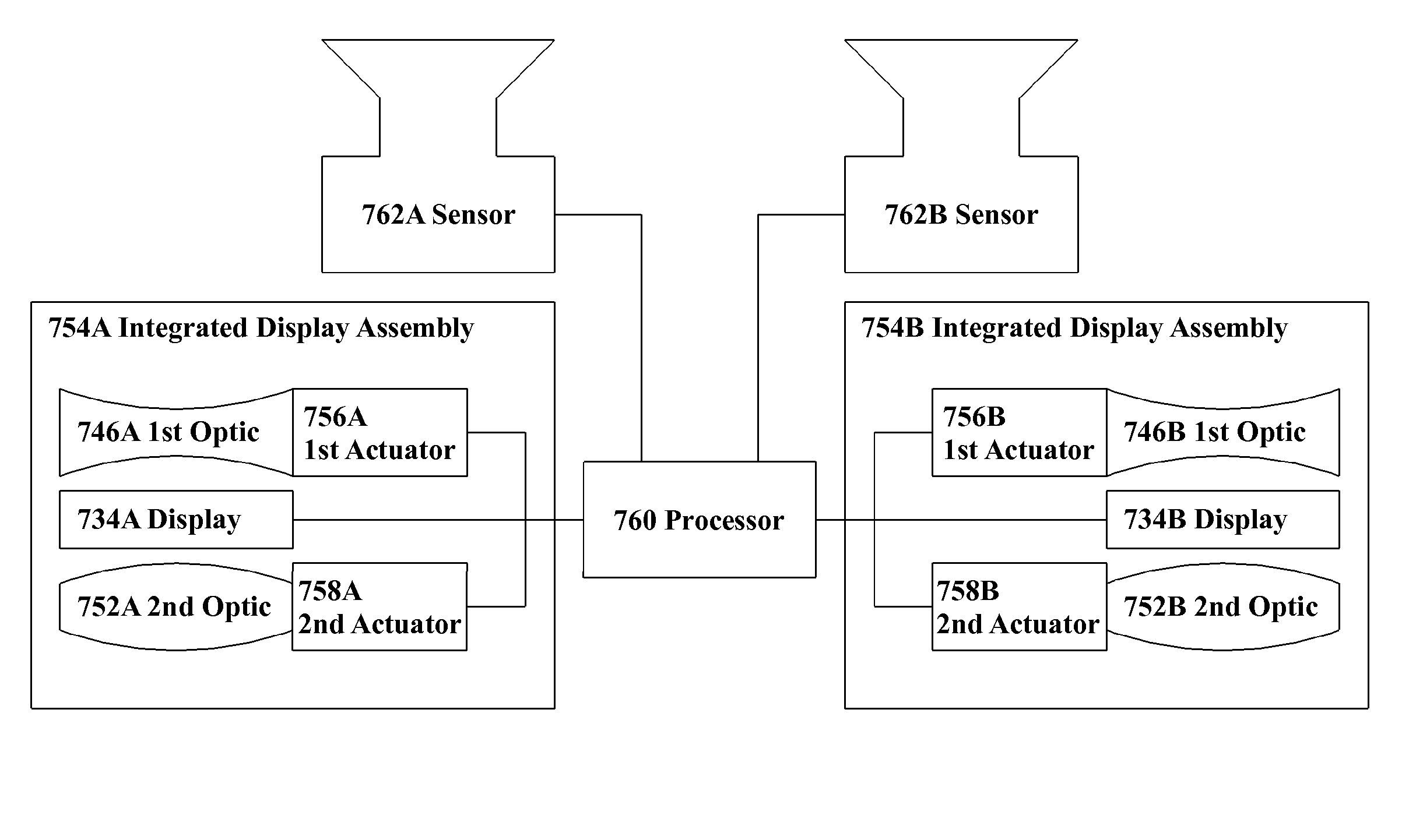
The present invention provides a system for controlling the focal vergence of output content and the environment content in a display. The system includes an apparatus with two optics that can alter the focal vergence of the output content and the environment content independently. The system can also include a see-through display that delivers the output content and the environment content to the same viewing position. The technical effects of the invention include the ability to control the focal vergence of the output content and the environment content, and the ability to adjust the degree of alteration of focal vergence of each optic. The system can also include a sensor to determine the distance between the optics and the focal vergence of the output content. The invention can be used in a variety of applications such as displays, head-mounted displays, and virtual and augmented reality devices.

Problems solved by technology

For at least such systems, controlling focal vergence of output content “upstream” from the display itself may be problematic.

Method used


Image

  • Method and apparatus for controlling focal vergence of optical content
  • Method and apparatus for controlling focal vergence of optical content
  • Method and apparatus for controlling focal vergence of optical content

Examples


Embodiment Construction

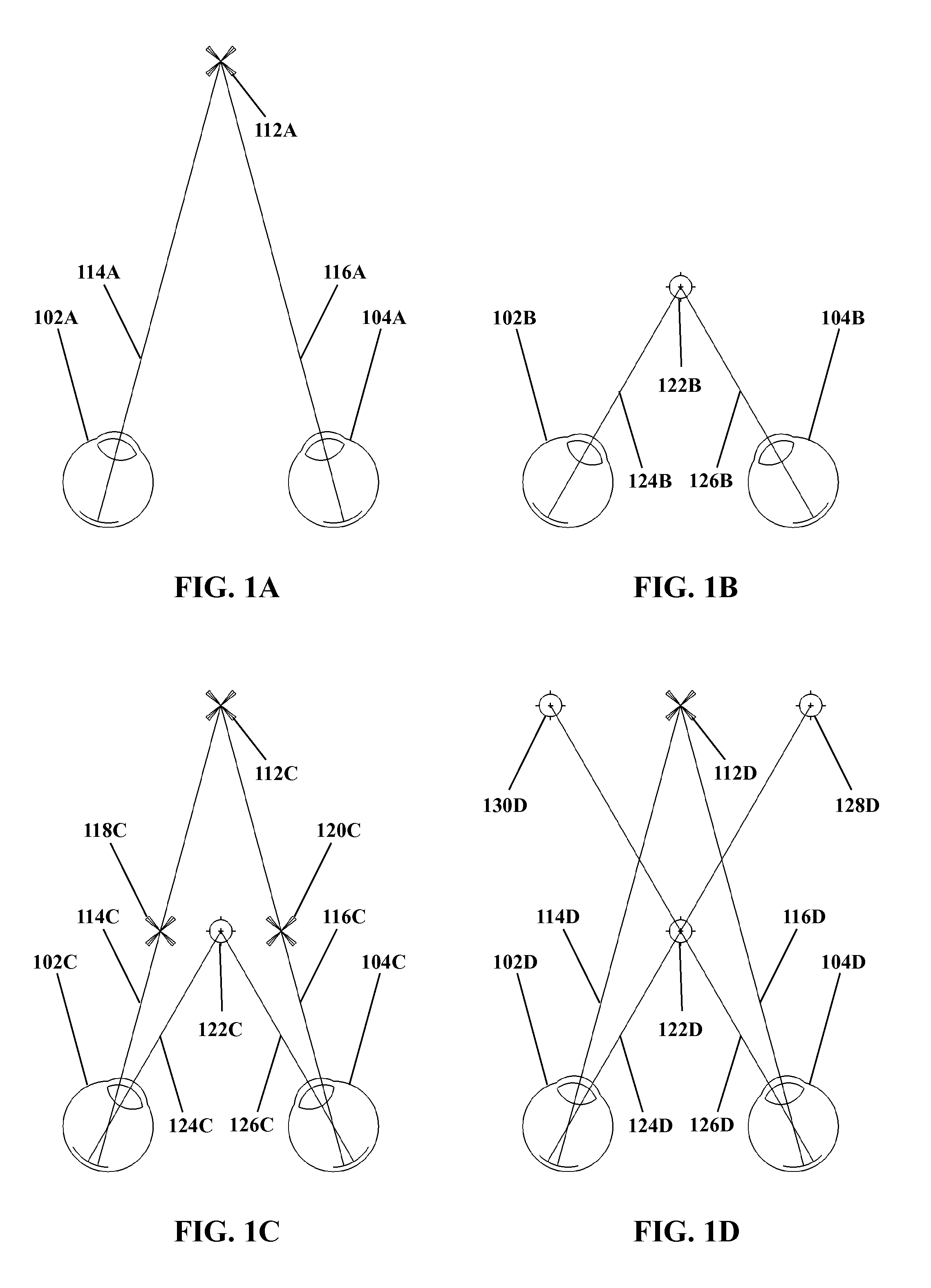
[0046]With reference to FIG. 1A, therein is shown an arrangement of sight lines for stereo vision of a target 112A. As may be seen, left and right sight lines 114A and 116A may be traced from the left and right eyes 102A and 104A respectively to the target 112A.

[0047]FIG. 1B shows an arrangement of sight lines to a target 122B. The arrangement in FIG. 1B is at least somewhat similar to that in FIG. 1A. However, as may be seen by comparison of FIG. 1A and FIG. 1B, the target 122B in FIG. 1B is at a different depth or distance with respect to the viewer (represented by eyes 102B and 104B) than is the target 112A from the viewer (represented by eyes 102A and 104A) in FIG. 1A. That is, the target 122B in FIG. 2B is closer to the viewer than the target 112A in FIG. 1A.

[0048]Even though the distance to the target 122B in FIG. 1B is less, a similar general arrangement may be observed: left and right sight lines 124B and 126B may be traced from the left and right eyes 102B and 104B respecti...


PUM


Abstract

A first optic receives optical environment content for delivery to the see-through display. The see-through display delivers output optical content to the second optic and delivers the optical environment content to the second optic. The second optic delivers the optical output content and optical environment content to a viewing position. The first optic alters the focal vergence of the optical environment content; the second optic alters the focal vergence of the optical environment content and the focal vergence of the optical output content. The focal vergences of the optical output content and optical environment content thus are independently controllable. The first and second optics may render the focal vergence of the optical environment content after first and second optics substantially equal to optical environment content unmodified by either the first or second optics. The focal vergences of optical environment content and output content may be equal after alteration.

Description

FIELD OF THE INVENTION[0001]The present invention relates to the control of focal vergence of optical content. More particularly, the present invention relates to controlling the focal vergence of content generated by and / or transmitted through a display system, without necessarily applying the same changes in focal vergence to both the generated and transmitted optical content.DESCRIPTION OF RELATED ART[0002]A variety of devices may deliver some form of generated optical content. For example, a head mounted display system may generate augmented reality content, such as information regarding position, speed, landmarks, etc. and deliver that content to a viewer. Such content typically has some degree focal vergence (whether convergent, divergent, or parallel), that is, the content is generated and / or displayed so as to have a focus that corresponds to some depth or distance from the viewer. For example, augmented reality content in a head mounted display might be delivered with a foc...

Claims


Application Information

Patent Timeline
Patent Type & Authority Applications(United States)
IPC IPC(8): G02B27/01G02B27/22
CPCG02B27/0101G02B2027/0134G02B2027/014G02B27/2228G02B27/0172G02B2027/0178G02B30/34
Inventor ITANI, SLEIMAN
Owner WEST TEXAS TECH PARTNERS LLC
Learn More