Package substrate and method for fabricating the same

Inactive Publication Date: 2015-11-19
SILICONWARE PRECISION IND CO LTD
View PDF5 Cites 0 Cited by
  • Summary
  • Abstract
  • Description
  • Claims
  • Application Information

AI Technical Summary

Benefits of technology

[0030]In summary, the present invention involves mounting a metal board to the first electrical connecting pads, and the metal board is patterned to form a plurality of metal pilla

Problems solved by technology

This grinding process may easily cause raw edges on the metal pillar, leading to short circuit of between the fine pitched metal pillars, resulting in yield reduction.
Moreover, if etching is used to substitute grinding

Method used


Image

  • Package substrate and method for fabricating the same
  • Package substrate and method for fabricating the same
  • Package substrate and method for fabricating the same

Examples


Embodiment Construction

[0034]The present invention is described in the following with specific embodiments, so that one skilled in the pertinent art can easily understand other advantages and effects of the present invention from the disclosure of the present invention.

[0035]FIGS. 2A-2I are cross-sectional views illustrating a method of fabricating a package substrate according to the present invention.

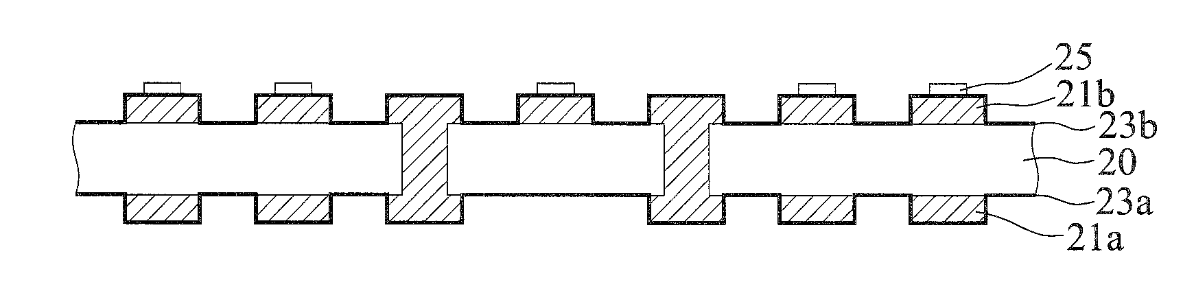
[0036]As shown in FIG. 2a, a substrate body 20 is provided that has a first surface 20a, a plurality of first electrical connecting pads 21a disposed on the first surface 20a, a first circuit 22a formed on the first surface 20a, a second surface 20b opposing the first surface 20a, a plurality of second electrical connecting pads 21b disposed on the second surface 20b, and a second circuits 22b formed on the second surface 20b. The substrate body 20 has a plurality of conductive vias 201 penetrating the first surface 20a and the second surface 20b and electrically connecting the first circuit 22a with the se...


PUM


Abstract

A package substrate and a method of fabricating the same are provided. The method includes providing a substrate body having a first surface, a second surface opposing the first surface, a plurality of first electrical connecting pads disposed on the first surface; mounting a metal board on the first electrical connecting pads; and patterning the metal board so as to define a plurality of metal pillars corresponding to the first electrical connecting pads. Therefore, drawbacks of raw edges and unequal heights of the metal pillars can be obviated.

Description

BACKGROUND OF THE INVENTION[0001]1. Field of the Invention[0002]The present invention relates to package substrates and a method for fabricating the same, and, more particularly, to a package on package (PoP) and a method for fabricating the same[0003]2. Description of Related Art[0004]Recently, with the increasingly smaller, lightweight and thinner profile in all types of electronic products, package on package (PoP) becomes increasingly popular.[0005]FIGS. 1A-1K are cross-sectional views of a method for fabricating a substrate used in PoP according to the prior art.[0006]As shown in FIG. 1A, a substrate 10 having a first surface 10a and a second surface 10b opposing the first surface 10a is provided. A plurality of first electrical connecting pads 11a and a first circuit 12a are disposed on the first surface 10a of the substrate 10. A plurality of second electrical connecting pads and a second circuit 12a are formed on the second surface 10a of the substrate 10. The substrate 10 h...

Claims


Application Information

Patent Timeline
IPC IPC(8): H01L23/00H01L23/48
CPCH01L24/17H01L23/481H01L24/09H01L2224/0219H01L24/11H01L2224/02185H01L24/03H01L21/4853H01L21/486H01L23/49811H01L23/49827H01L2924/0002
Inventor PAI, YU-CHENGLIN, CHUN- HSIENCHIU, SHIH-CHAOHSIAO, WEI-CHUNGSUN, MING-CHENSHEN, TZU-CHIEHCHEN, CHIA-CHENG
Owner SILICONWARE PRECISION IND CO LTD
Why Eureka
Try Eureka