
Ultra-low-temperature device and method for refrigerating object to be refrigerated using the same

Active Publication Date: 2015-11-26
KOBE STEEL LTD
View PDF3 Cites 12 Cited by
  • Summary
  • Abstract
  • Description
  • Claims
  • Application Information

AI Technical Summary

Benefits of technology

The present invention provides an ultra-low-temperature device that can efficiently refrigerate an object by using a refrigeration device including a cold head and a cold head insertion unit. The cold head insertion unit allows for highly efficient heat transfer with the object to be refrigerated while effectively suppressing the infiltration of heat into the object. The device also includes a heat switch that can be switched between an on state and an off state to allow or block the conduction of heat between the cold head and the object to be refrigerated. The method for refrigerating an object using the ultra-low-temperature device involves inserting the cold head into the cold head insertion unit, forming a thermal coupling part by solidifying a heat conduction medium, and turning on the heat switch.

Problems solved by technology

In the device that is described in Patent Literature 1, it is difficult to prevent infiltration of heat into the objects to be refrigerated when removing the cold head 104.

Method used


Image

  • Ultra-low-temperature device and method for refrigerating object to be refrigerated using the same
  • Ultra-low-temperature device and method for refrigerating object to be refrigerated using the same
  • Ultra-low-temperature device and method for refrigerating object to be refrigerated using the same

Examples


Embodiment Construction

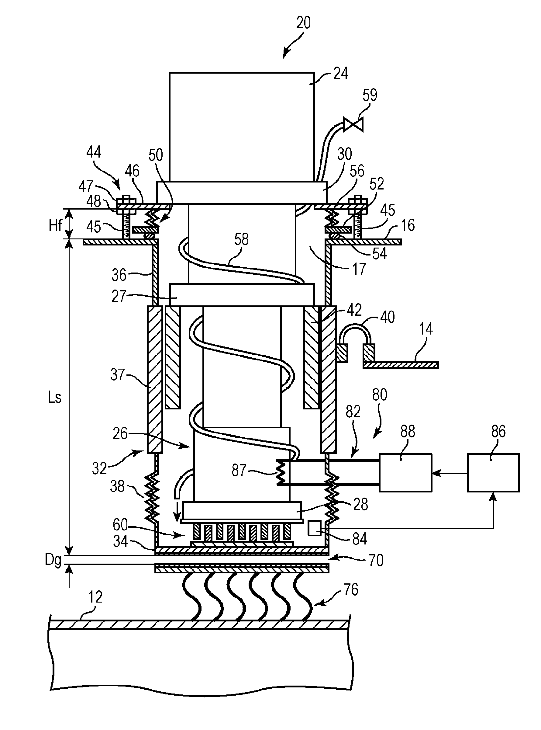
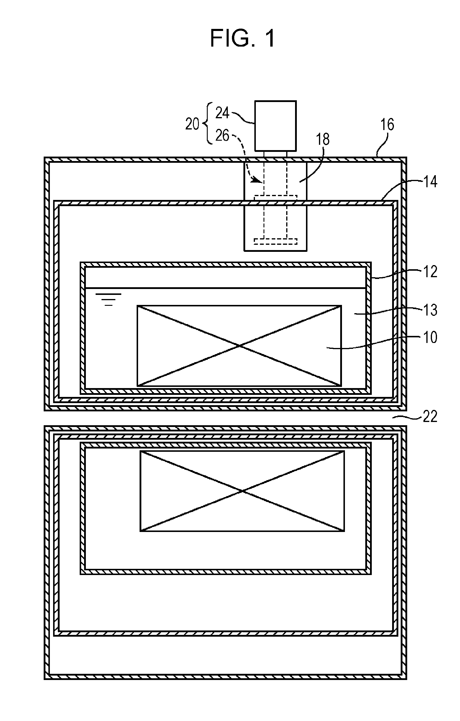
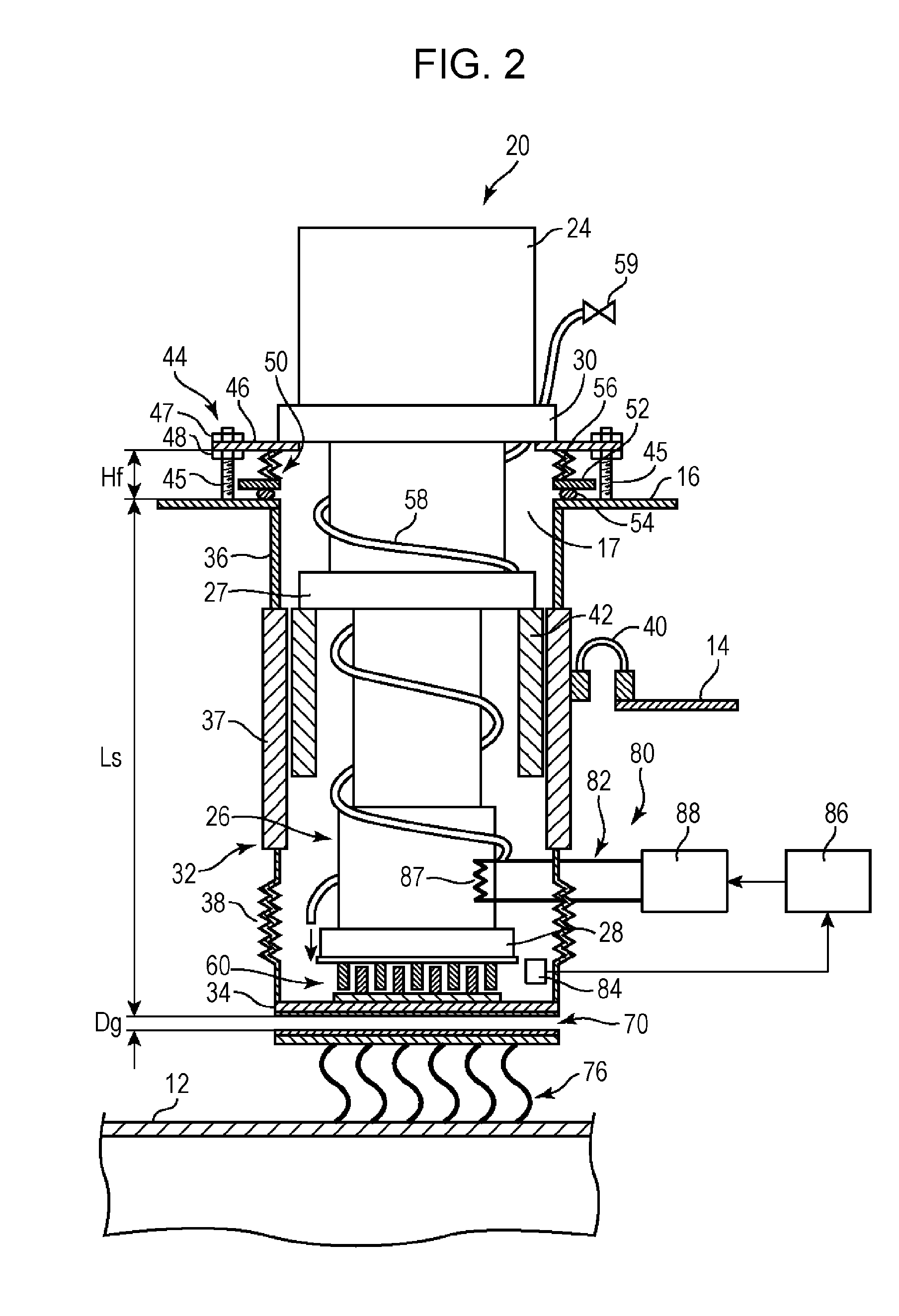
[0017]An embodiment of the present invention is described with reference to the drawings. An ultra-low-temperature device according to the embodiment is a superconducting magnet device, and includes, as objects to be refrigerated, a superconducting magnet 10 and a liquid helium container 12 that contains the superconducting magnet 10. The superconducting magnet 10 and the liquid helium container 12 are refrigerated by a refrigeration device 20. However, the present invention is not limited to these types of objects to be refrigerated. The present invention is applicable to refrigeration of a SQUID magnetometer and other superconducting elements.

[0018]In addition to the superconducting magnet 10 and the liquid helium container 12, the device shown in FIG. 1 includes a heat shield container 14 that contains the liquid helium container 12, a vacuum container 16 that contains the heat shield container 14 and whose interior is in a vacuous state, and a cold head insertion unit 18.

[0019]A...


PUM


Abstract

Provided is an ultra-low-temperature device that enables the cold head of a refrigeration device to be coupled in a detachable manner so as to be capable of highly efficient heat transfer with respect to an object being cooled, while effectively suppressing the infiltration of heat into the object being cooled. This ultra-low-temperature device is equipped with; a cooled object container (16); a cold head insertion unit (18) having a cylindrical part (32) and a base part (34); a thermal coupling formation part (60) forming a thermal coupling part between the low-temperature end (28) of the cold head (26) and the base part (34); and a heat switch (70) provided between the base part (34) and the cooled object (12). The thermal coupling formation part (60) has refrigeration-device side recesses and protrusions (61, 62) and insertion-unit-side recesses and protrusions (63, 64), with the thermal coupling part being formed by the freezing of a gaseous heat transfer medium in the gaps (66) between these recesses and protrusions. The heat switch (70) has an insertion-unit-side heat switch element provided on the base part (34), and a cooled-body-side switch element, and the transfer of heat is enabled or prevented on the basis of whether the switch elements are in contact or are separated from each other.

Description

TECHNICAL FIELD [0001]The present invention relates to an ultra-low-temperature device for refrigerating an object to be refrigerated, such as a superconducting magnet, by using a refrigeration device, and to a method for refrigerating the object to be refrigerated by using the ultra low-temperature device.BACKGROUND ART [0002]Hitherto, as an ultra-low-temperature device for refrigerating an object to be refrigerated, such as a superconducting magnet or a liquid helium container that contains the superconducting magnet, an ultra-low-temperature device that uses a refrigeration device including a cold head has been known. In this ultra-low-temperature device, how efficiently the cold head is coupled to an object to be refrigerated (that is, bow small the thermal resistance can be made) and whether or not the cold head can be made separable from the object to be refrigerated are important subjects.[0003]Patent Literature 1 discloses a device that uses a low-boiling gas, such as nitrog...

Claims


Application Information

Patent Timeline
IPC IPC(8): F25D3/10
CPCF25D3/10F25B9/00H01F6/04F25B9/10F25D19/006F25B2400/17F25B9/14
Inventor MIKI, TAKASHI
Owner KOBE STEEL LTD
Learn More