Dialysis system and methods

a technology of dialysis system and dialysis method, which is applied in the field of dialysis system, can solve the problems of patient backflow, patient fatigue, and patient uncompromising schedule, and achieve the effect of preventing backflow of blood

Inactive Publication Date: 2015-12-03
OUTSET MEDICAL
View PDF2 Cites 12 Cited by
  • Summary
  • Abstract
  • Description
  • Claims
  • Application Information

AI Technical Summary

Benefits of technology

[0010]A method of achieving dynamic balancing with a dialysis system is also provided, comprising operating a blood pump to move a flow of blood from a patient through a patient tubing set and a blood-side of a dialyzer, measuring a venous pressure of the patient, operating a first dialysate pump and a second dialysate pump to move a flow of dialysate through a dialysate-side of the dialyzer, preventing a flow of dialysate from passing through the dialysate-side of the dialyzer, while the flow of dialysate through the dialysate-side of the dialyzer is prevented, measuring a dialysate pressure between the first dialysate pump and the second dialysate pump, and adjusting a pump speed of the second dialysate pump until the measured dialysate pressure stabilizes, allowing the flow of dialysate to pass through the dialysate-side of the dialyzer, and adjusting a pump speed of the second dialysate pump to create a flow imbalance between the first and second dialysate pumps that results in a flow of fluid between the blood-side of the dialyzer and the dialysate-side of the dialyzer to equalize the flow imbalance.
[0017]A dialysis system is provided, comprising a dialyzer comprising a blood-side and a dialysate-side, a blood circuit coupled to the blood-side of the dialyzer and further comprising a venous line adapted to be connected to an venous connection site of a patient and an arterial line adapted to be connected to an arterial connection site of the patient, a blood pump coupled to the blood circuit and configured to move blood from the patient, through the arterial line, through the blood-side of the dialyzer, and through the venous line back into the patient, a venous pressure sensor coupled to the blood circuit and configured to measure a venous pressure of the patient, a dialysate circuit coupled to the dialysate-side of the dialyzer and further comprising a dialysate line coupled to a dialysate source, an actuator coupled to the dialysate circuit, the actuator comprising a first configuration in which dialysate moves through the dialysate-side of the dialyzer and a second configuration in which dialysate is prevented from moving through the dialysate-side of the dialyzer, a first dialysate pump and a second dialysate pump coupled to the dialysate circuit and configured to move dialysate from the dialysate source, through the dialysate line, and through the dialysate-side of the dialyzer when the actuator is in the first configuration, a dialysate pressure sensor coupled to the dialysate circuit and configured to measure a pressure of the dialysate between the first dialysate pump and the second dialysate pump, an electronic controller operatively coupled to the blood pump, the venous pressure sensor, the dialysate pressure sensor, the actuator, the first dialysate pump, and the second dialysate pump, the electronic controller being configured to achieve dynamic balancing of fluid flow across the dialyzer during dialysis therapy by performing the steps of adjusting a pump speed of the first dialysate pump to move a flow of dialysate through the dialysate-side of the dialyzer, controlling the actuator to prevent the flow of dialysate from moving through the dialysate-side of the dialyzer, receiving the measured dialysate pressure from the dialysate pressure sensor, and adjusting a pump speed of the second dialysate pump until the measured dialysate pressure stabilizes, controlling the actuator to allow the flow of dialysate to move through the dialysate-side of the dialyzer, and adjusting a pump speed of the second dialysate pump to create a flow imbalance between the first and second dialysate pumps that results in a flow of fluid between the blood-side of the dialyzer and the dialysate-side of the dialyzer to equalize the flow imbalance.
[0049]In another embodiment, the heparin line is coupled to the venous drip chamber at a non-pulsatile location to prevent back streaming of blood into the heparin line during therapy.

Problems solved by technology

Many patients receive dialysis treatment at a dialysis center, which can place a demanding, restrictive and tiring schedule on a patient.
Moreover, in-center patients must follow an uncompromising schedule as a typical center treats three to five shifts of patients in the course of a day.
As a result, many people who dialyze three times a week complain of feeling exhausted for at least a few hours after a session.
The inefficiencies of most dialysis systems and the need for significant technician involvement in the process make it even more difficult for patients to receive dialysis therapy away from large treatment centers.
Unfortunately, current dialysis systems are generally unsuitable for use in a patient's home.
One reason for this is that current systems are too large and bulky to fit within a typical home.
Current dialysis systems are also energy-inefficient in that they use large amounts of energy to heat large amounts of water for proper use.
Although some home dialysis systems are available, they generally use complex flow-balancing technology that is relatively expensive to manufacture and most systems are designed with a system of solenoid valves that create high noise levels.

Method used


Image

  • Dialysis system and methods
  • Dialysis system and methods
  • Dialysis system and methods

Examples


Embodiment Construction

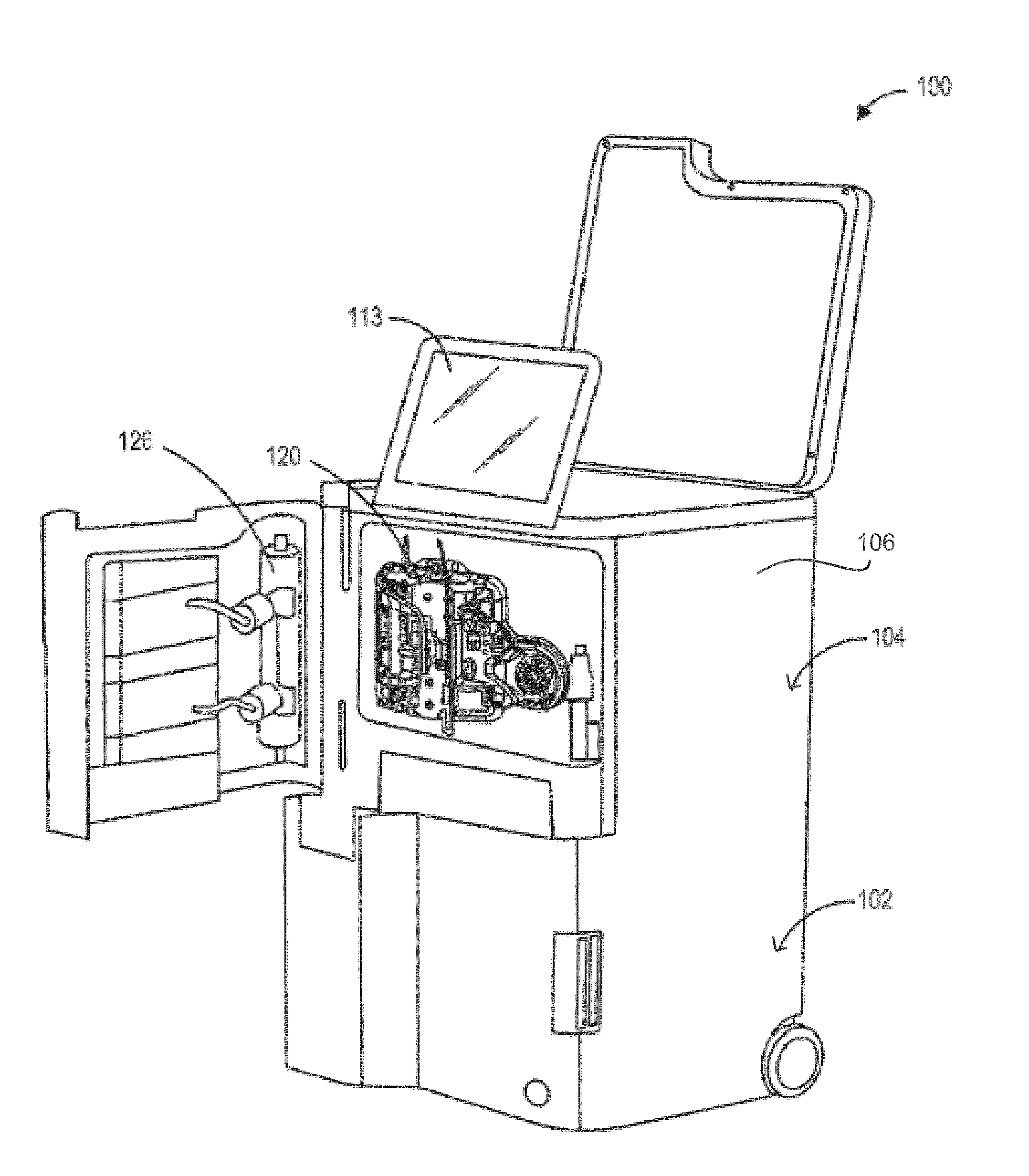
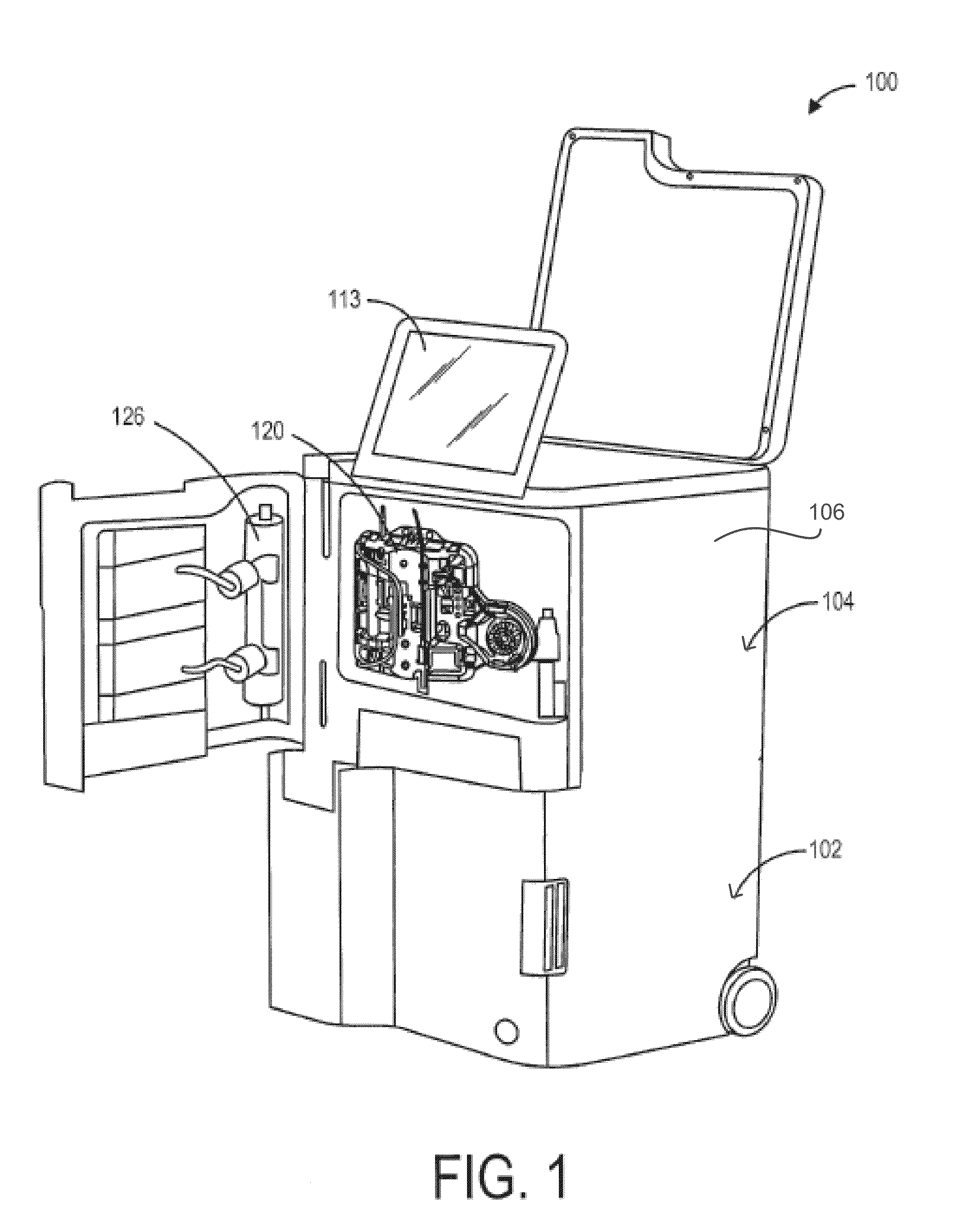
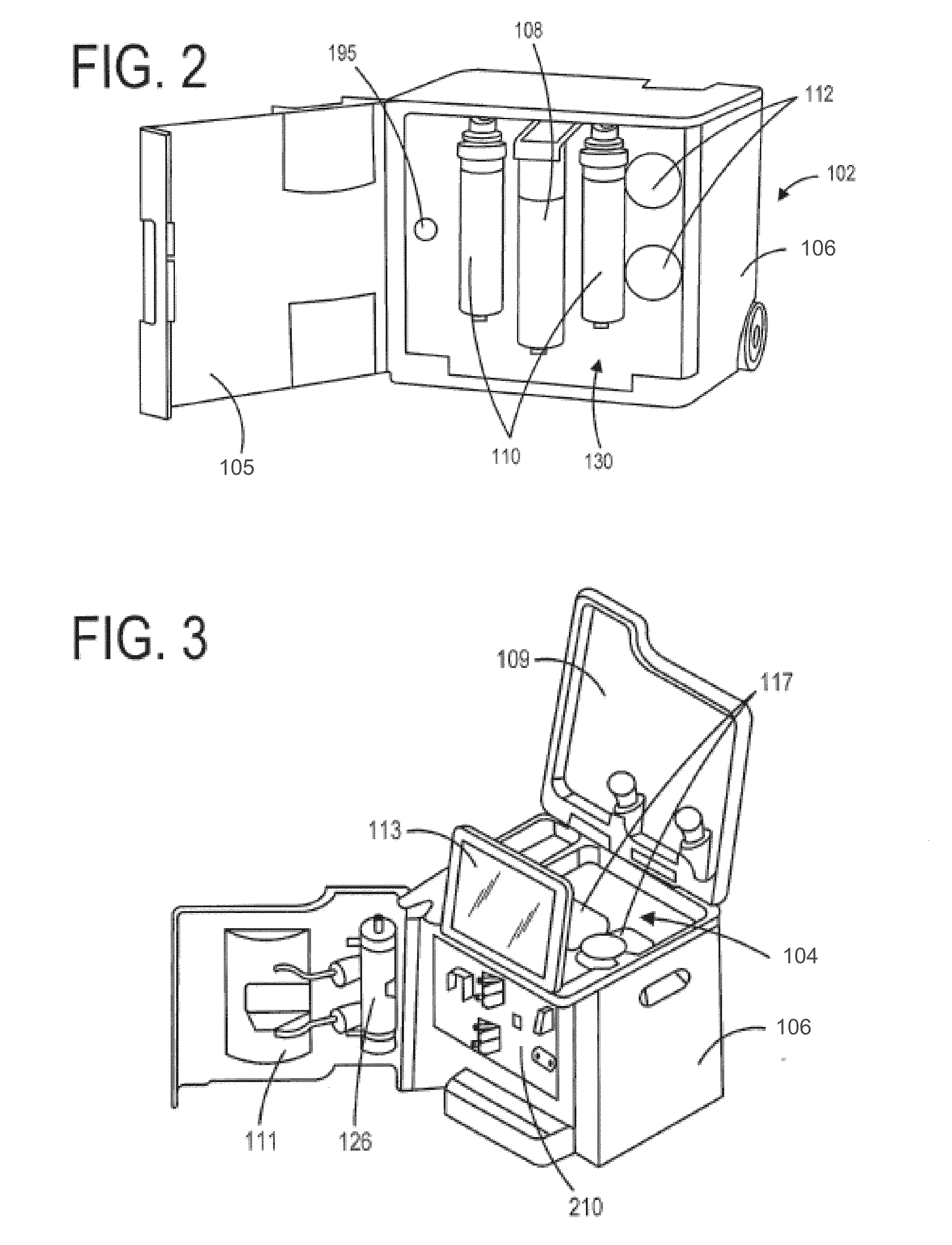
[0074]This disclosure describes systems, devices, and methods related to dialysis therapy, including a dialysis system that is simple to use and includes automated features that eliminate or reduce the need for technician involvement during dialysis therapy. In some embodiments, the dialysis system can be a home dialysis system. Embodiments of the dialysis system can include various features that automate and improve the performance, efficiency, and safety of dialysis therapy.

[0075]In some embodiments, a dialysis system is described that can provide acute and chronic dialysis therapy to users. The system can include a water purification system configured to prepare water for use in dialysis therapy in real-time using available water sources, and a dialysis delivery system configured to prepare the dialysate for dialysis therapy. The dialysis system can include a disposable cartridge and tubing set for connecting to the user during dialysis therapy to retrieve and deliver blood from ...


PUM

PropertyMeasurementUnit
timeaaaaaaaaaa
pressure dropaaaaaaaaaa
flow rateaaaaaaaaaa

Abstract

Dialysis systems and methods are described which can include a number of features. The dialysis systems described can be to provide dialysis therapy to a patient in the comfort of their own home. The dialysis system can be configured to prepare purified water from a tap water source in real-time that is used for creating a dialysate solution. The dialysis systems described also include features that make it easy for a patient to self-administer therapy. For example, the dialysis systems include disposable cartridge and patient tubing sets that are easily installed on the dialysis system and automatically align the tubing set, sensors, venous drip chamber, and other features with the corresponding components on the dialysis system. Methods of use are also provided, including automated priming sequences, blood return sequences, and dynamic balancing methods for controlling a rate of fluid transfer during different types of dialysis, including hemodialysis, ultrafiltration, and hemodiafiltration.

Description

CROSS REFERENCE TO RELATED APPLICATIONS[0001]This application is a continuation of pending U.S. application Ser. No. 14 / 699,875, filed Apr. 29, 2015, which application claims the benefit of U.S. Provisional Application No. 61 / 985,779, filed Apr. 29, 2014, titled “Air Removal in Modular Home Dialysis System”, and also claims the benefit of U.S. Provisional Application No. 62 / 127,155, filed Mar. 2, 2015, titled “Dialysis System”, both of which are incorporated herein by reference.INCORPORATION BY REFERENCE[0002]All publications and patent applications mentioned in this specification are herein incorporated by reference to the same extent as if each individual publication or patent application was specifically and individually indicated to be incorporated by reference.FIELD[0003]This disclosure generally relates to dialysis systems. More specifically, this disclosure relates to dialysis systems that include many features that reduce the need for technician involvement in the preparatio...

Claims


Application Information

Patent Timeline
Patent Type & Authority Applications(United States)
IPC IPC(8): A61M1/16
CPCA61M1/1603A61M2205/3341A61M2202/0413A61M1/165A61M1/1656A61M1/1686A61M2205/123A61M2205/18A61M2205/3673A61M2230/30A61M1/3646A61M1/3644A61M1/1658A61M1/166A61M1/1672A61M1/3649A61M1/3647Y10T29/49782Y10T29/49897Y10T137/0424A61M1/3643A61M2205/3365A61M1/362265A61M1/362262A61M1/36224A61M1/36222A61M1/362266A61M1/36225A61M1/1621A61M2205/121A61M2205/14B01D19/0063
Inventor HOGARD, MICHAEL EDWARDLINGAM, GOPIHU, DEANMANIAM, BALAJI M.RITSON, JAMESUCHIDA, ANDY H.STIENMIER, JOHN DAVIDMCGREGOR, PAUL DAVID
Owner OUTSET MEDICAL
Why Eureka
Try Eureka