Oil separator

a technology of oil separator and separator plate, which is applied in the direction of separation process, dispersed particle separation, air treatment device, etc., can solve problems such as operation defects, and achieve the effect of reducing the vertical height of such an installation spa

Active Publication Date: 2015-12-03
NABTESCO AUTOMOTIVE CORP
View PDF3 Cites 8 Cited by
  • Summary
  • Abstract
  • Description
  • Claims
  • Application Information

AI Technical Summary

Benefits of technology

[0006]Installation of an oil separator in an air dryer requires a space for installing the air dryer and the oil separator. Particularly, the vertical height of such an installation space has been desired to be reduced.

Problems solved by technology

When the compressed air containing such water and oil enters inside the systems, it causes rust and swelling of rubber members (such as O-rings) and results in an operational defect.

Method used


Image

  • Oil separator
  • Oil separator
  • Oil separator

Examples


Embodiment Construction

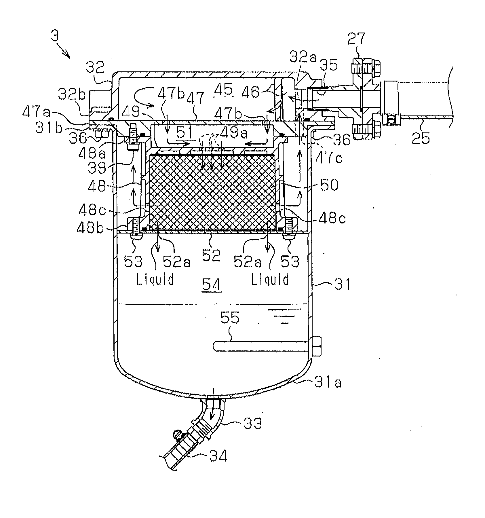
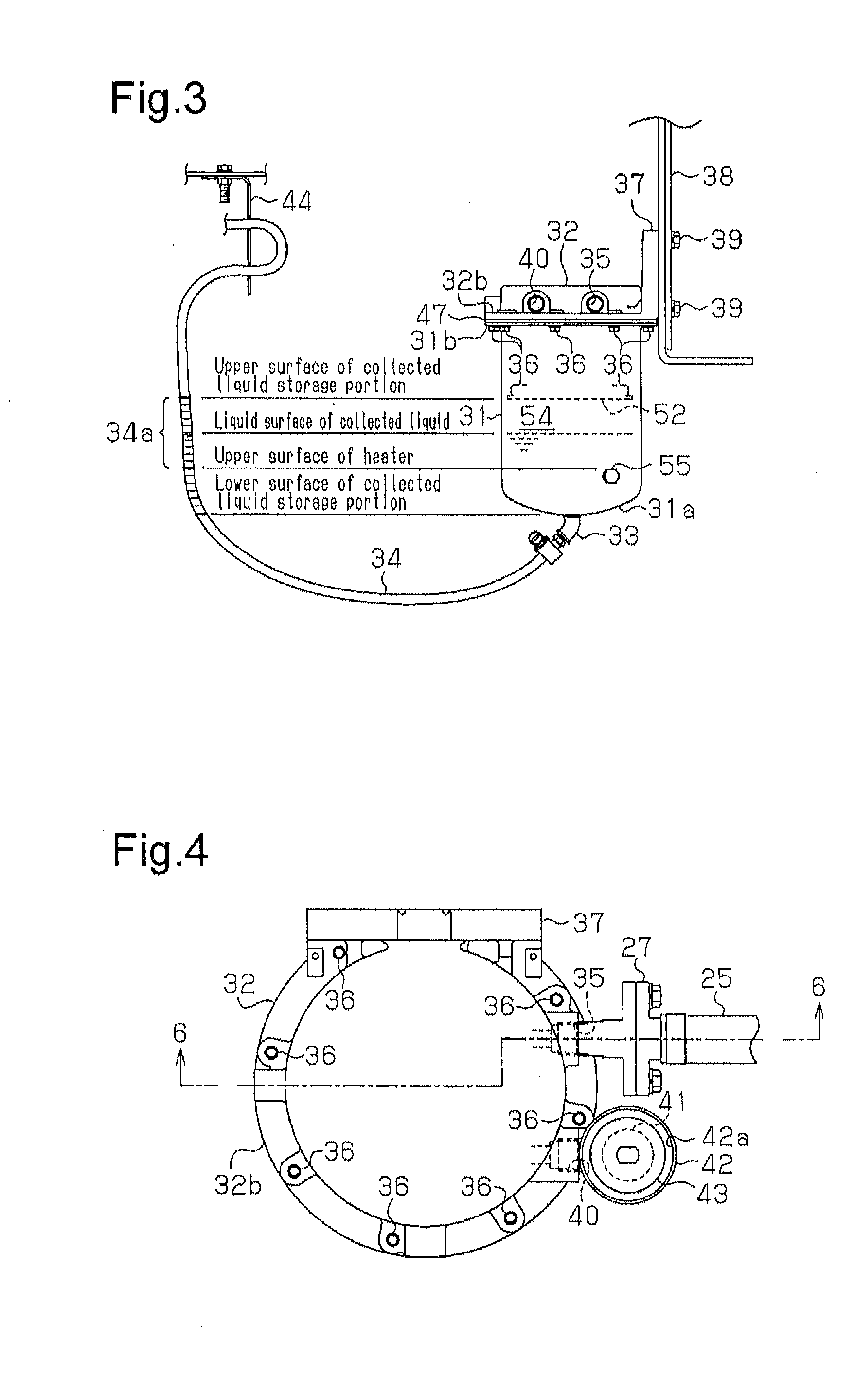
[0015]An oil separator according to the present invention will now be described with reference to FIGS. 1 to 5. The oil separator is applied to an exhaust system of an air dryer.

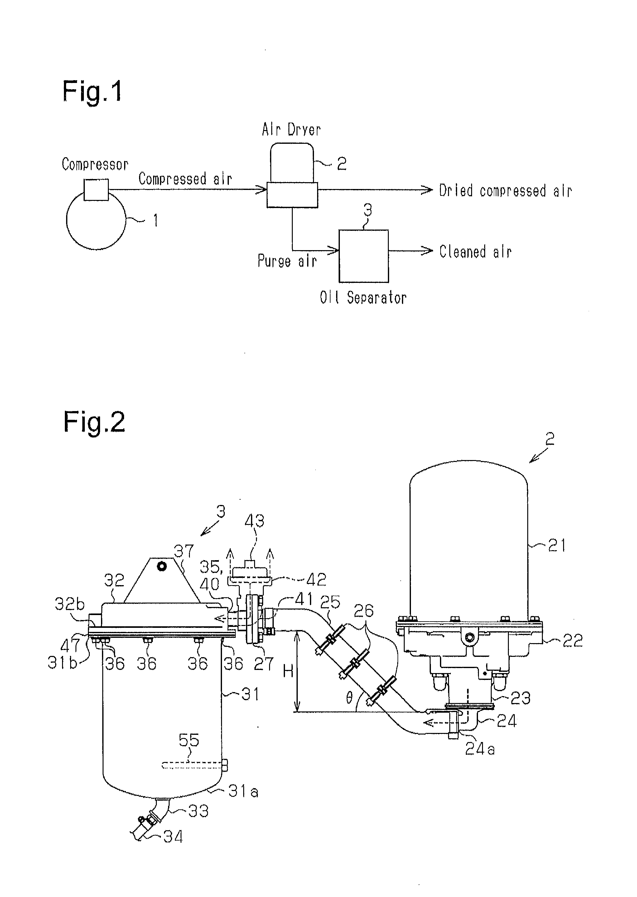
[0016]As shown in FIG. 1, vehicles such as trucks, buses, and construction machines utilize compressed air delivered by a compressor 1 to control systems such as brakes and suspensions. Thus, an air dryer 2, which removes oil and water in the compressed air and provides dried air, is located downstream of the compressor 1 of an air system. The air dryer 2 contains desiccant. The air dryer 2 performs dehumidification to remove oil and water from the compressed air and regeneration to regenerate the desiccant by removing the oil and water adsorbed by the desiccant and discharging them to the outside.

[0017]In the present embodiment, since air (purge air) discharged from the air dryer 2 during regeneration of the desiccant includes oil together with water, an oil separator 3 is provided downstream of the compres...


PUM

PropertyMeasurementUnit
angleaaaaaaaaaa
heightaaaaaaaaaa
angleaaaaaaaaaa

Abstract

An oil separator is provided with a casing having an inlet for air and an outlet for air, an expansion chamber for expanding air introduced therein through the inlet, an accommodation member communicating with the expansion chamber in the vertical direction, a collected liquid storage portion provided below the accommodation member, and a connecting hose having an oil separator connection end for being connected to the inlet and an air dryer connection end for being connected to an air dryer. The connecting hose is configured such that the oil separator connection end is located higher than the air dryer connection end.

Description

TECHNICAL FIELD[0001]The present invention relates to an oil separator that separates oil contained in air that has passed through equipment.BACKGROUND ART[0002]Vehicles such as trucks, buses, and construction machines utilize compressed air delivered by a compressor, which is directly connected to the engine, to control systems such as brakes and suspensions. The compressed air contains water, which is contained in the atmosphere, and oil for lubricating the inside of the compressor. When the compressed air containing such water and oil enters inside the systems, it causes rust and swelling of rubber members (such as O-rings) and results in an operational defect. Thus, an air dryer is provided downstream of the compressor in an air system for removing water and oil from the compressed air (for example, Patent Document 1).[0003]A filter and a desiccant such as silica gel and zeolite are provided in the air dryer. The air dryer performs dehumidification to remove water from compresse...

Claims


Application Information

Patent Timeline
Patent Type & Authority Applications(United States)
IPC IPC(8): B01D45/08
CPCB01D45/08B60T17/004B01D53/261
Inventor SUGIO, TAKUYAMINATO, ICHIRO
Owner NABTESCO AUTOMOTIVE CORP
Why Eureka
Try Eureka