

Harness clamp
- Summary
- Abstract
- Description
- Claims
- Application Information
AI Technical Summary
Benefits of technology
Problems solved by technology
Method used
Image

Examples
first embodiment
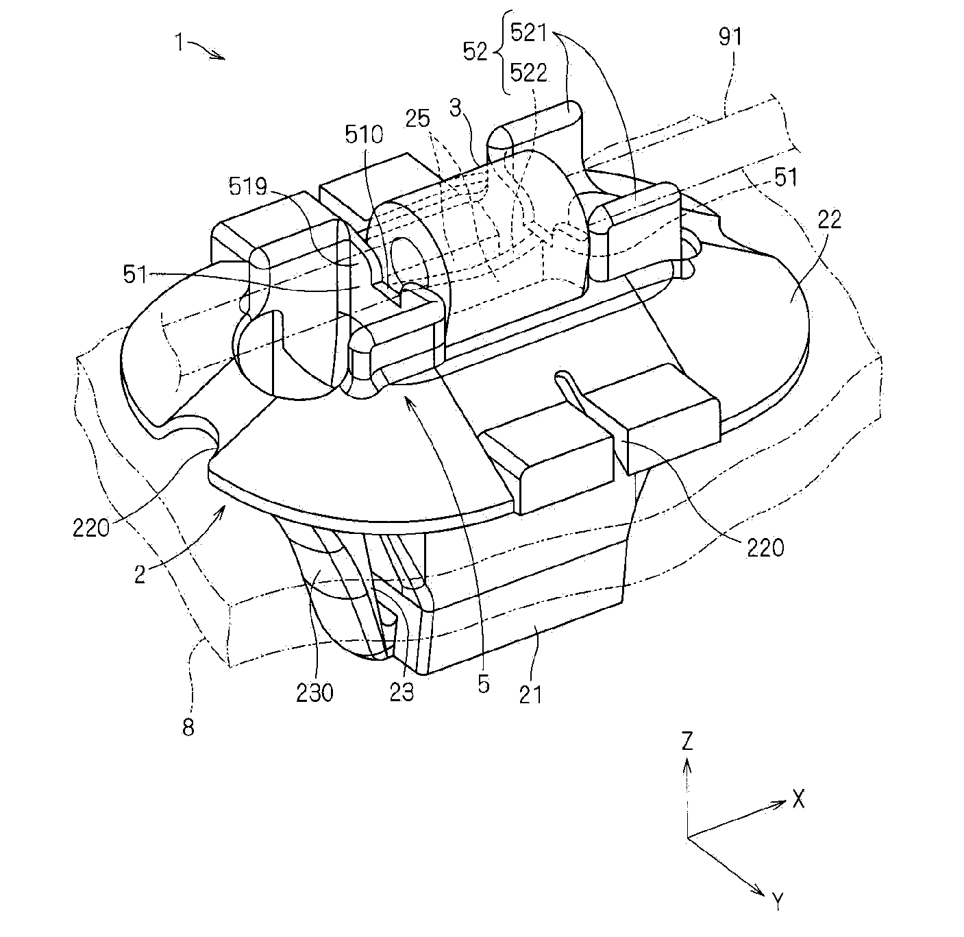
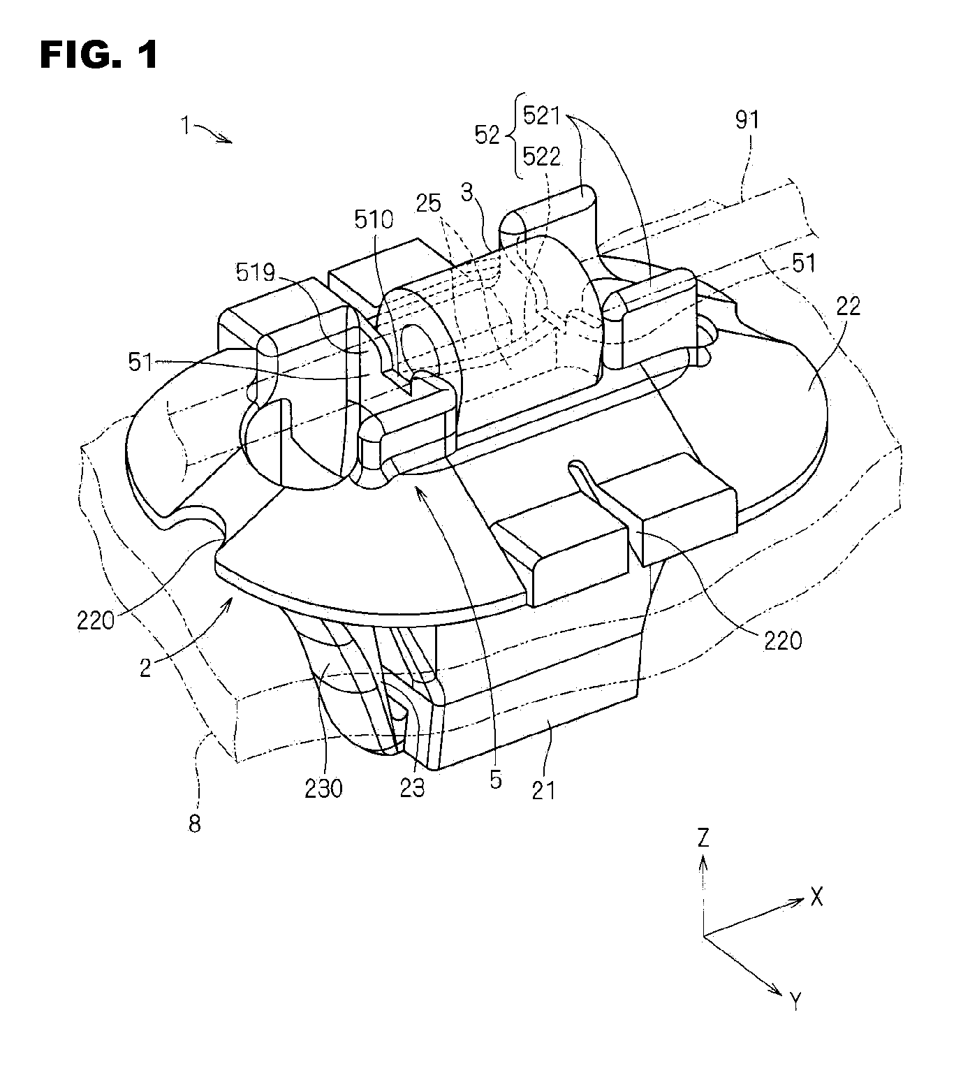
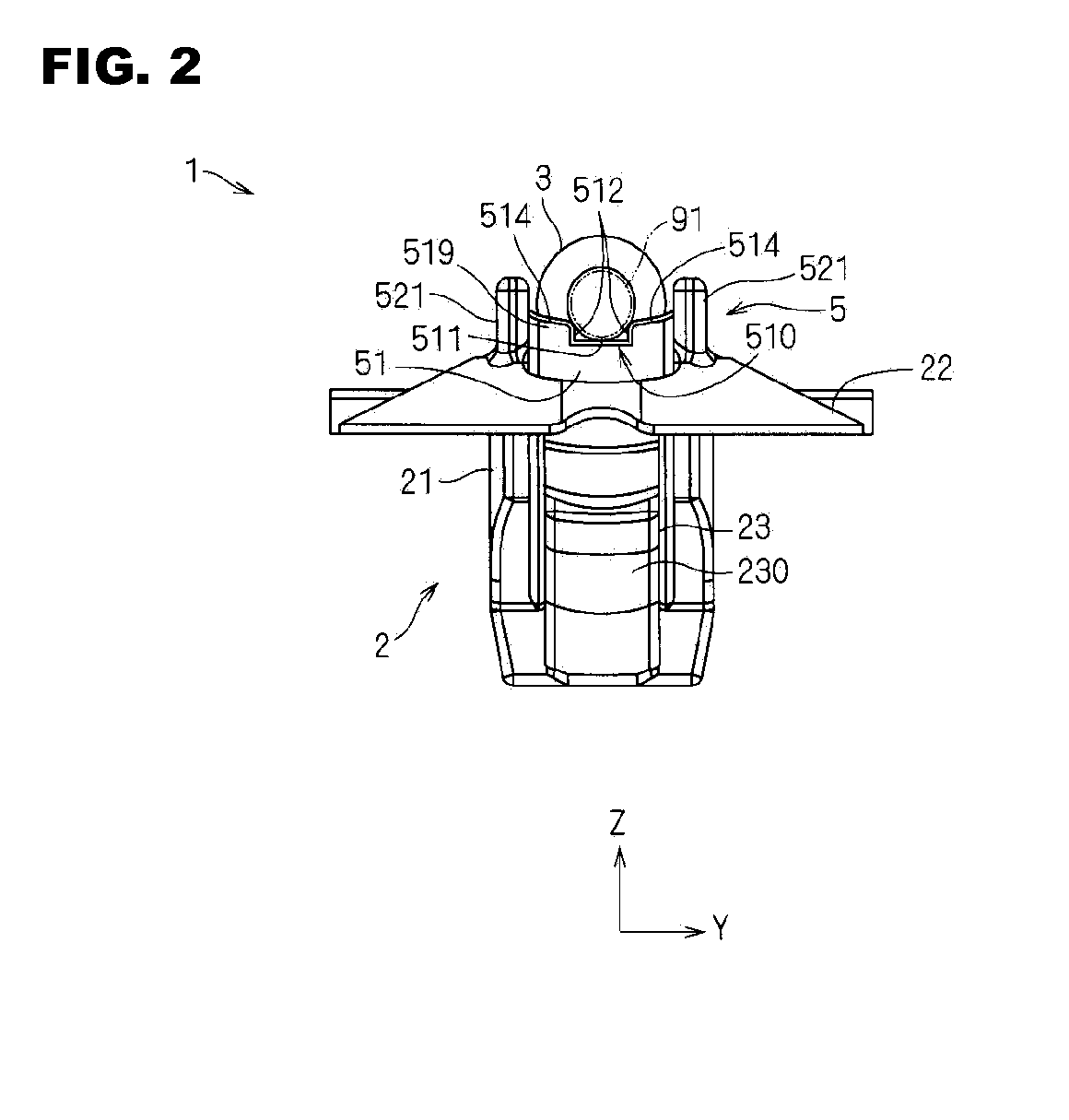
[0032]A harness clamp 1 according to this embodiment will be described with reference to FIGS. 1 to 6. The harness clamp 1 fixes an electric wire 91 or an electric wire bundle 92 to a fixing counterpart portion 8. It should be noted that FIGS. 1 to 3 shows that the harness clamp 1 fixes an electric wire 91 and FIG. 6 shows that the harness clamp 1 fixes an electric wire bundle 92.
[0033]In this embodiment, one example of the fixing counterpart portion 8 is a metal panel constituting a vehicle body. In this embodiment, a case will be described in which the harness clamp 1 is fixed to a fixing counterpart portion 8 provided with a hole (referred to as “fixing hole” hereinafter) that penetrates the fixing counterpart portion 8 in the thickness direction and that is used for fixing the harness clamp 1.
Harness Clamp
[0034]The harness clamp 1 includes a fixing portion 2, a belt portion 3, and a belt locking portion 4. The harness clamp 1 is formed by, for example, injection molding a synthe...
second embodiment
[0083]Next, a harness clamp 1A according to a second embodiment will be described with reference to FIG. 8. The harness clamp 1A is different from the harness clamp 1 in that the belt portion 3 and the fixing portion 2 are formed in one piece. It should be noted that in FIG. 8, the components identical to the components shown in FIGS. 1 to 7 are denoted by identical reference numerals. Hereinafter, the difference between the harness clamp 1A and the harness clamp 1 will be described.
[0084]In this embodiment, the belt portion 3 is formed such that one end thereof is continuous with the fixing portion 2. The other end of the belt portion 3 serves as a free end. Hereinafter, the end portion serving as a free end in the belt portion 3 is referred to as “lock side end portion 3A”.
[0085]In this embodiment, the fixing portion 2 is provided with one belt inserting hole portion 25. Moreover, the belt locking portion 4 is provided inside the belt inserting hole portion 25.
[0086]In this embodi...
application examples
[0089]In the above-described embodiments, a form has been described in which the recessed portions 510 of the wall portions 51 suppress the rotation of the harness clamp 1 around the electric wire 91, whereas the pairs of bilateral auxiliary wall portions 521 suppress the rotation of the harness clamp 1 around the electric wire bundle 92. However, the recessed portions 510 of the wall portions 51 may also suppress the rotation of the harness clamp 1 around an electric wire bundle 92 including a relatively small number of electric wires, whereas the pairs of bilateral auxiliary wall portions 521 may also suppress the rotation of the harness clamp 1 around an electric wire bundle 92 including a relatively large number of electric wires, or the recessed portions 510 of the wall portions 51 may also suppress the rotation of the harness clamp 1 around an electric wire 91 having a relatively small diameter, whereas the pairs of bilateral auxiliary wall portions 521 may also suppress the r...
PUM
 Abstract
Description
Claims
Application Information