Bearing and bearing device

Active Publication Date: 2017-06-15
TAIHO INDUSTRIES CO LTD
View PDF1 Cites 0 Cited by
  • Summary
  • Abstract
  • Description
  • Claims
  • Application Information

AI Technical Summary

Benefits of technology

[0014]With the present invention, the rotation of the bearing can be suppressed without the necessity of a projecting portion on the outer circumferential surface of the arc portion in the bearing.
[0015]1 . . . Steering device, 10 . . . Bushing, 11 . . . Arc portion, 12 . . . Rotation suppressing

Problems solved by technology

In general, use of an arc-shaped bearing causes a problem in that the bearing easily rotates; that i

Method used


Image

  • Bearing and bearing device
  • Bearing and bearing device
  • Bearing and bearing device

Examples


Example

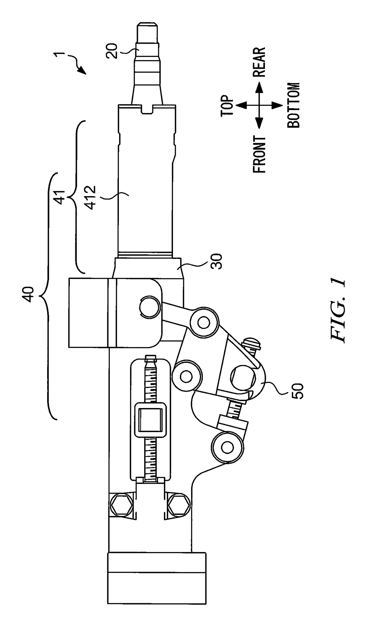
[0021]FIG. 1 is a diagram showing the external appearance of steering device 1 according to an embodiment. Steering device 1 is an example of a bearing device using bushing 10 (an example of a bearing) according to an embodiment, and is used in an automobile. Steering device 1 includes steering shaft 20, housing 30, telescopic mechanism 40, and tilt mechanism 50.

[0022]Steering shaft 20 transmits the rotation of a steering wheel (not shown) to a steering gearbox (not shown). Steering shaft 20 is accommodated in housing 30. Telescopic mechanism 40 is a mechanism for adjusting the position of the steering wheel in the front-rear direction (in the axial direction of steering shaft 20; in the horizontal direction in FIG. 1). Tilt mechanism 50 is a mechanism for adjusting the position of the steering wheel in the vertical direction (in a direction orthogonal to the axial direction of steering shaft 20; in the vertical direction in FIG. 1). The telescopic mechanism and the tilt mechanism a...


PUM


Abstract

The rotation of a bearing is suppressed without the need for a projecting portion on an outer circumferential surface of an arc portion in the bearing. Bearing 10 includes arc portion 11 in which a cross section orthogonal to an axial direction has an arc shape, and rotation suppressing portion 12 and rotation suppressing portion 13 that extend respectively from a first end and a second end of an arc in arc portion 11 and include a portion projecting outward from a circumcircle of arc portion 11 in the cross section orthogonal to the axial direction.

Description

TECHNICAL FIELD[0001]The present invention relates to a bearing and a bearing device.BACKGROUND ART[0002]A technique that uses an arc-shaped bearing rather than a cylindrical bearing as a bearing for supporting a movable column member of a steering shaft in a steering device of a vehicle is known (Patent Documents 1 and 2, for example). In general, use of an arc-shaped bearing causes a problem in that the bearing easily rotates; that is, the bearing shifts due to the application of force in the circumferential direction of the shaft. In order to address this, in Patent Documents 1 and 2, a large projecting portion is formed on the outer circumferential surface of a resin bearing, a recessed portion that meshes with the projecting portion is formed in a housing, and rotation of the bearing is prevented due to the meshing between the projecting portion and the recessed portion.CITATION LISTPatent Documents[0003]Patent Document 1: JP 2013-67310A[0004]Patent Document 2: JP 2013-67313ASU...

Claims


Application Information

Patent Timeline
IPC IPC(8): F16C17/02F16C35/02F16C33/14F16C33/20B62D1/181F16C33/08
CPCF16C17/022B62D1/181F16C35/02F16C33/14F16C33/20F16C33/08F16C17/02
Inventor ARASAKI, SHINYA
Owner TAIHO INDUSTRIES CO LTD
Why Eureka
Try Eureka