
Cable protection and guide apparatus

Active Publication Date: 2013-02-07
TSUBAKIMOTO CHAIN CO
View PDF21 Cites 4 Cited by
  • Summary
  • Abstract
  • Description
  • Claims
  • Application Information

AI Technical Summary

Benefits of technology

The cable protection and guide apparatus includes a link row group and first and second connecting arms that are connected at a hinge structure. This hinge structure enables the connecting arm to rotate on the axis of rotation. The apparatus has a rotation restricting portion that restricts the rotation of the connecting arm in the disconnected condition. This restricting rotation angle allows for efficient insertion of cables and hoses into the accommodating space. The apparatus also includes multiple link rows, which provide flexual bending lanes for cables and hoses. The link plates are connected at a flexational inner and outer circumferential side and can rotate during bending. The apparatus ensures efficient and safe protection and guidance of cables and hoses.

Problems solved by technology

Thus, it is difficult to make the hinge stem and the hook smaller.
Still further, when the first connecting arm is in the connected condition and the second connecting arm is in the disconnected condition with respect to one pair of link plates and when the cables are inserted in the accommodating space in a condition in which the accommodating space is opened upward with the first connecting arm being a bottom, the accommodating space lacks integrity when inserting the cables therein.
Thus, there is a problem that it takes extra time to insert the cables into the accommodating space.
Still further, when the hook is removed from or attached to the hinge stem or when an operator forcibly engages or disengages the disengagement preventing engage portions, there is a problem that parts including the engaging portions that rub with each other wear quickly.
Still further, if a gap greater than a minute gap necessary for rotation is created between the hinge stem and the hook, an abutment (or rattling) is caused between the hinge stem and the hook in rotating the connecting arm and the connecting arm is not smoothly rotated.
Therefore, there are problems that wear is increased where the hinge stem abuts the hook and that it takes time to rotate the arm.

Method used


Image

  • Cable protection and guide apparatus
  • Cable protection and guide apparatus
  • Cable protection and guide apparatus

Examples


embodiment

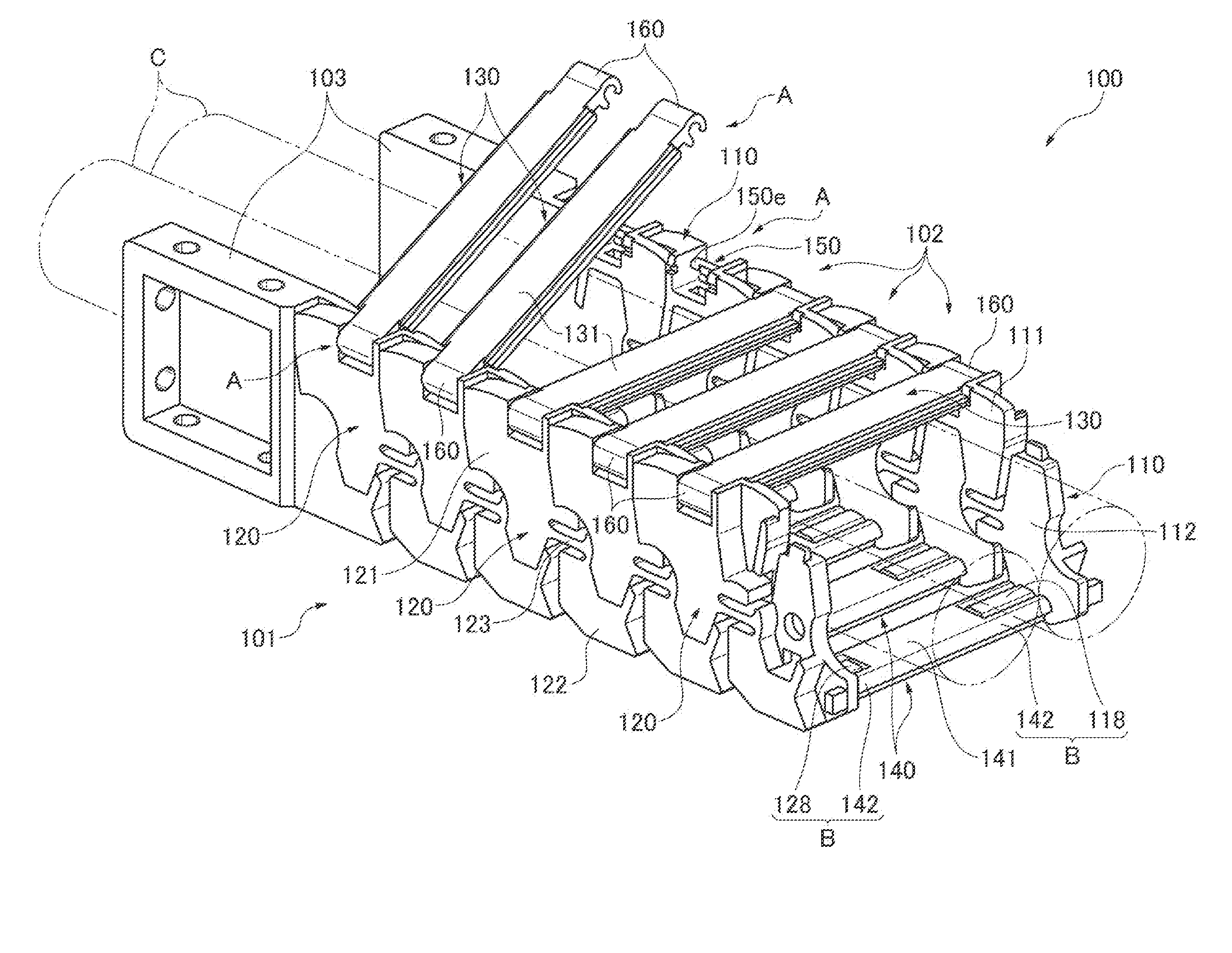
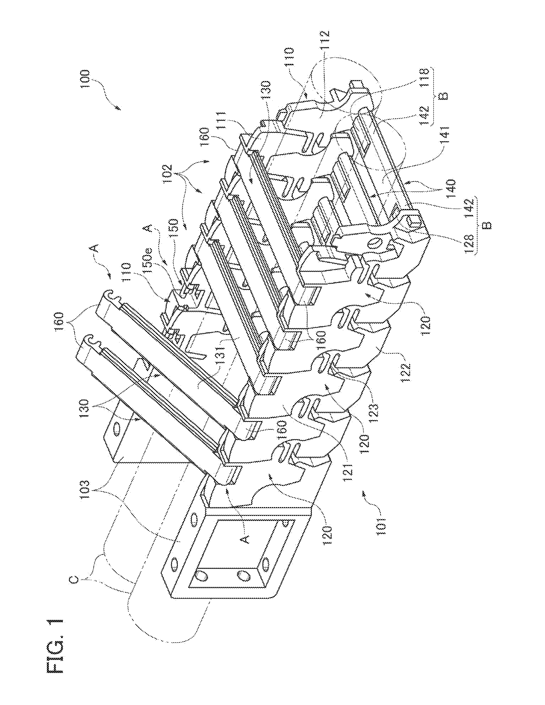
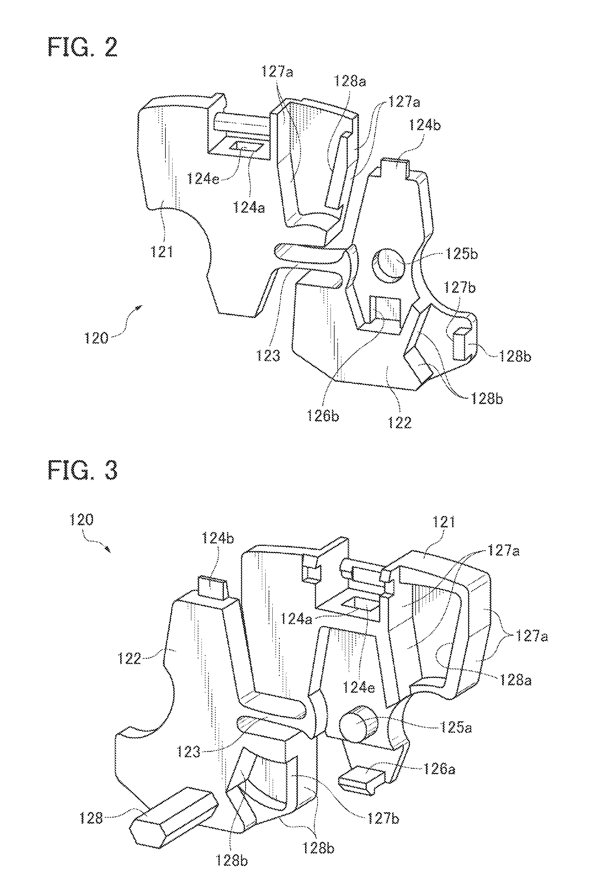
[0082]An embodiment of a cable protection and guide apparatus of the invention will be explained with reference to FIGS. 1 through 10.

[0083]The cable protection and guide apparatus 100 (referred to simply as ‘guide apparatus’ or ‘apparatus’ hereinafter) of the embodiment of the invention shown in FIG. 1 is included in a machine not shown that includes cables and / or hoses and is used to protect and guide the cables and / or hoses. The machines described above include semiconductor equipment, pharmaceutical medicine testing apparatuses, vehicular door opening / shutting devices, work machines and the like.

[0084]In order to accommodate the movable cables and / or hoses in the machine described above, the cable protection and guide apparatus 100 is configured to have flexibility so as to be able to take straight or bending posture locally or as a whole corresponding the movements of the cables and / or hoses between the movable portion and the stationary portion of the apparatus.

[0085]The cable...


PUM


Abstract

There is provided a cable protection and guide apparatus that improves efficiency of cable insertion and maintenance when a connecting arm attached to a link plate by a hinge structure is disconnected. In order to removably connect the connecting arm to the link plate, the guide apparatus has the hinge structure composed of a hinge stem and a hook that is rotatably engaged with the hinge stem. The hinge structure has a disengagement preventing portion that prevents the hook from disengaging from the hinge stem and a rotation restricting portion that restricts the rotation of the connecting arm in the disconnected condition. The rotation restricting portion is composed of a link-side engagement element and an arm-side engagement element. In the rotation restricting condition effected by engagement of the link-side and arm-side engagement elements, a rotational angle of the connecting arm is an obtuse angle.

Description

CROSS REFERENCE TO RELATED APPLICATIONS[0001]This application claims the foreign priority benefit under Title 35, United States Code, §119 (a)-(d) of Japanese Patent Application No. 2011-170393, filed on Aug. 3, 2011 in the Japan Patent Office, the disclosure of which is herein incorporated by reference in its entirety.BACKGROUND OF THE INVENTION[0002]1. Field of the Invention[0003]The present invention relates to a cable protection and guide apparatus configured to accommodate, protect and guide cables and hoses.[0004]2. Related Art[0005]The cable protection and guide apparatus comprises a plurality of link rows connected in a longitudinal direction and pluralities of first and second connecting arms. Each link row includes a pair of link plates separately disposed in a lateral direction from each other. The link plates adjoining in the longitudinal direction are connected articulately and bendably.[0006]Cables are accommodated within an accommodating space formed by the pair of li...

Claims


Application Information

Patent Timeline
IPC IPC(8): F16L3/12
CPCH02G11/006H02G3/0468F16G13/16H02G11/00B25J19/00
Inventor KOMIYA, SHOICHIRO
Owner TSUBAKIMOTO CHAIN CO
Learn More