Eureka AIR delivers breakthrough ideas for toughest innovation challenges, trusted by R&D personnel around the world.

Method for measuring motor brake health

Active Publication Date: 2019-03-28
ROCKWELL AUTOMATION TECH
View PDF9 Cites 0 Cited by
  • Summary
  • Abstract
  • Description
  • Claims
  • Application Information

AI Technical Summary

Benefits of technology

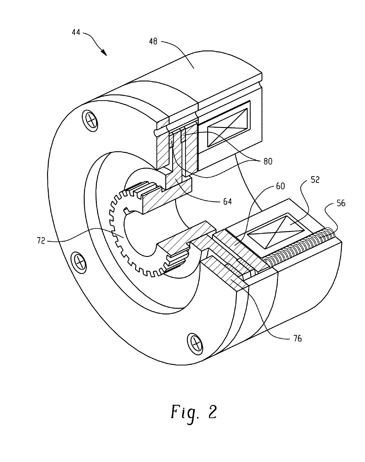
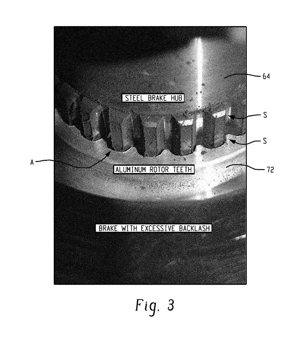
This patent describes a motor assembly with a position feedback device that can measure the angle of the motor's output shaft, and a brake assembly that can be engaged to restrict the rotation of the output shaft. The motor controller can apply a torque to the output shaft while the brake assembly is engaged, and measure the angular position of the output shaft during this process. By measuring the difference between the two positions, the amount of backlash between the brake rotor and brake hub can be determined. Overall, this technology allows for more precise control and monitoring of the motor's output and brake assembly performance.

Problems solved by technology

Over time, operation of the rotary servo motor results in wear on one or more of the brake assembly components.
However, identifying the root cause of maintenance issues (e.g., performing manual diagnostics) may be difficult and time-consuming, and precautionary replacement or repair of components on a set schedule can be inefficient.

Method used


Image

  • Method for measuring motor brake health
  • Method for measuring motor brake health
  • Method for measuring motor brake health

Examples


Embodiment Construction

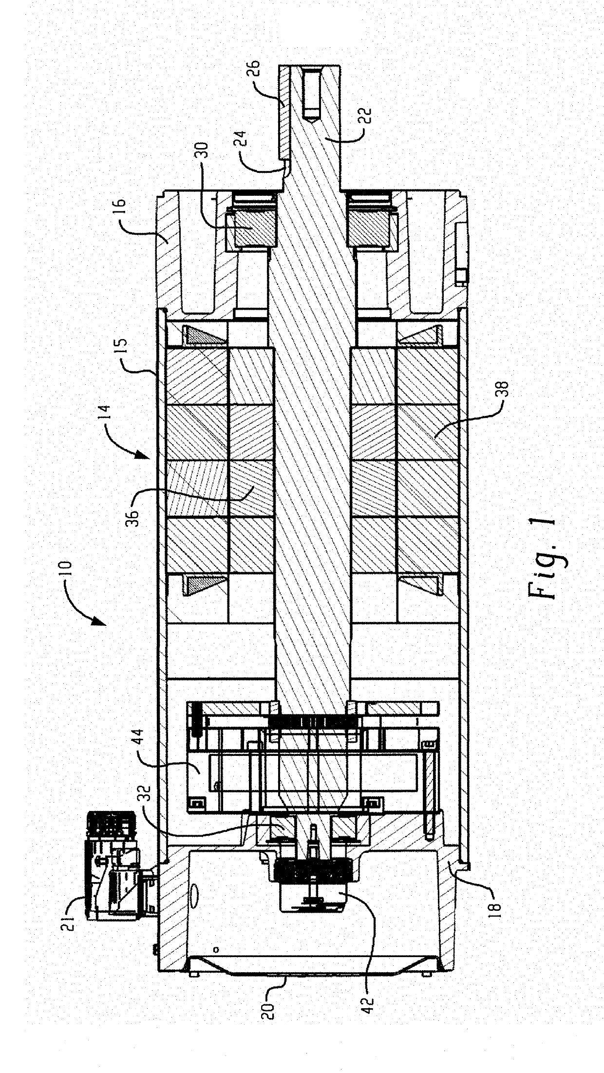
[0017]With reference to FIG. 1, an exemplary motor assembly is illustrated and identified generally by reference numeral 10. It will be appreciated that aspects of the present disclosure are applicable to a wide variety of electric motor configurations, as well as other applications where a rotating shaft is present (e.g., pumps, etc.). Accordingly, it should be understood that many of the features of the motor are exemplary in nature and intended to give context to certain aspects of the disclosure.

[0018]The exemplary motor assembly 10 generally includes a housing 14 for supporting and / or enclosing the various internal components of the motor 10, as will be described below. The housing 14 includes a main tubular portion 15, a front bearing support / front plate 16 and rear bearing support 17, and an end cap 20. Together, these housing components form a sealed internal chamber (or multiple chambers) for housing, among other things, the rotating elements of the motor, related circuitry...


PUM


Abstract

A motor assembly and method for measuring brake backlash using onboard components of the motor assembly. The method includes engaging a brake of the motor assembly, applying torque to an output shaft of the motor assembly in first and second rotational directions and measuring a difference in angular position of the output shaft using a position feedback device of the motor to calculate brake backlash.

Description

BACKGROUND INFORMATION[0001]Rotary servo motors are widely known and used to provide rotary motion control for industrial machinery and other applications. A rotor rotates relative to a stator in response to control input commands from a motor drive. An output shaft of the servo motor is operably connected to the rotor to rotate therewith. The output shaft projects outwardly from or is otherwise accessible at the motor housing at a front end. An encoder is operatively associated with the output shaft of the motor at an opposite rear end of the motor housing and provides feedback to the motor drive as to the angular position of the output shaft and rotor such that rotation of the output shaft is further controlled in response to the feedback to obtain a precise desired angular position for the rotor and output shaft connected thereto. Servo motors often further include a holding brake assembly or parking brake assembly that is selectively applied after the rotor is stopped in the des...

Claims


Application Information

Patent Timeline
IPC IPC(8): G01L5/28
CPCG01L5/28H02P1/166H02P3/04F16D2066/006
Inventor SUBASINGHE, MADDUMAGE P.SANDS, JOSEPH M.RAO, KANAGALA S.
Owner ROCKWELL AUTOMATION TECH
Why Eureka
Eureka Blog
Learn More