Mounting structure and clip

Active Publication Date: 2019-09-19
NIFCO INC +2
View PDF0 Cites 1 Cited by
  • Summary
  • Abstract
  • Description
  • Claims
  • Application Information

AI Technical Summary

Benefits of technology

[0022]At the clip, the axial center of the first shaft portion and the axial center of the second shaft portion are eccentric with respect to one another. Therefore, the relative positions of the first member and the second member can be adjusted around the first shaft portion or the second shaft portion. Further, at the clip, the cross-sectional shape of the portion, which is disposed at the inner side of the first-through hole, of the first shaft portion is a polygonal shape. The length along the longest diagonal line of the polygonal shape, or the length of the longest side of the polygonal shape, is longer than the minimum opening length of the first through-hole. Therefore, when the first member rotates with respect to th

Problems solved by technology

Therefore, it is difficult to maintain a state in which the relativ

Method used


Image

  • Mounting structure and clip
  • Mounting structure and clip
  • Mounting structure and clip

Examples


Embodiment Construction

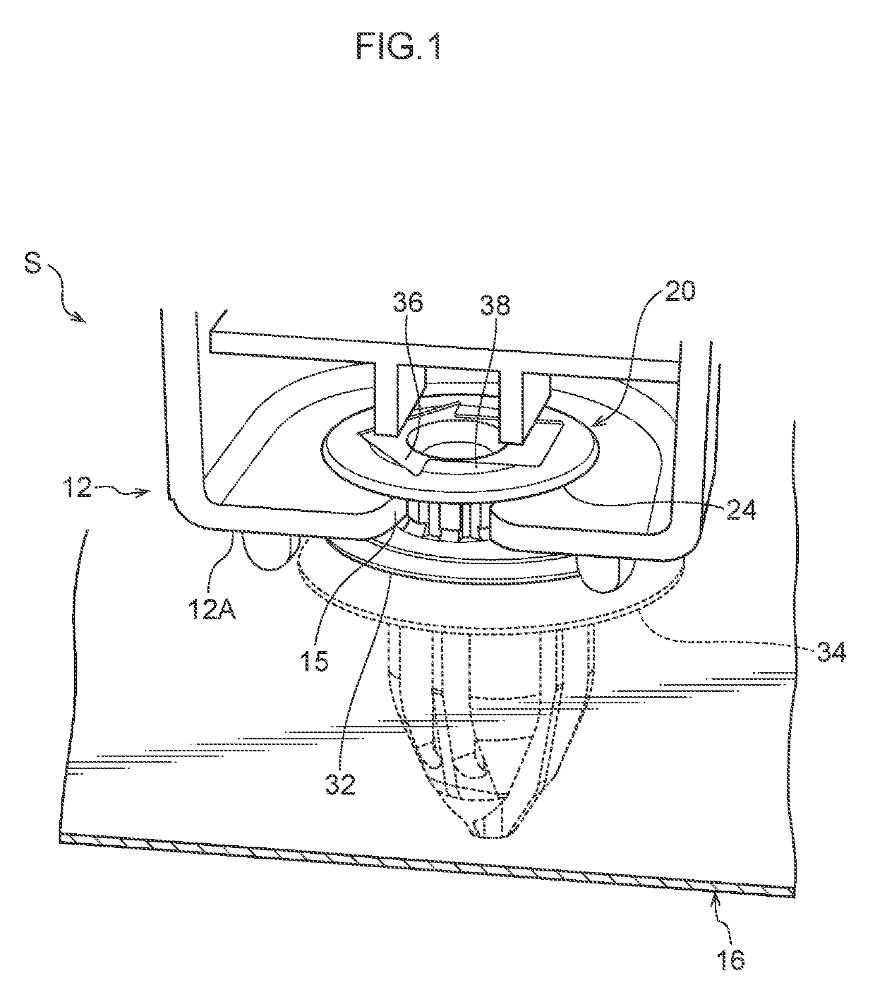
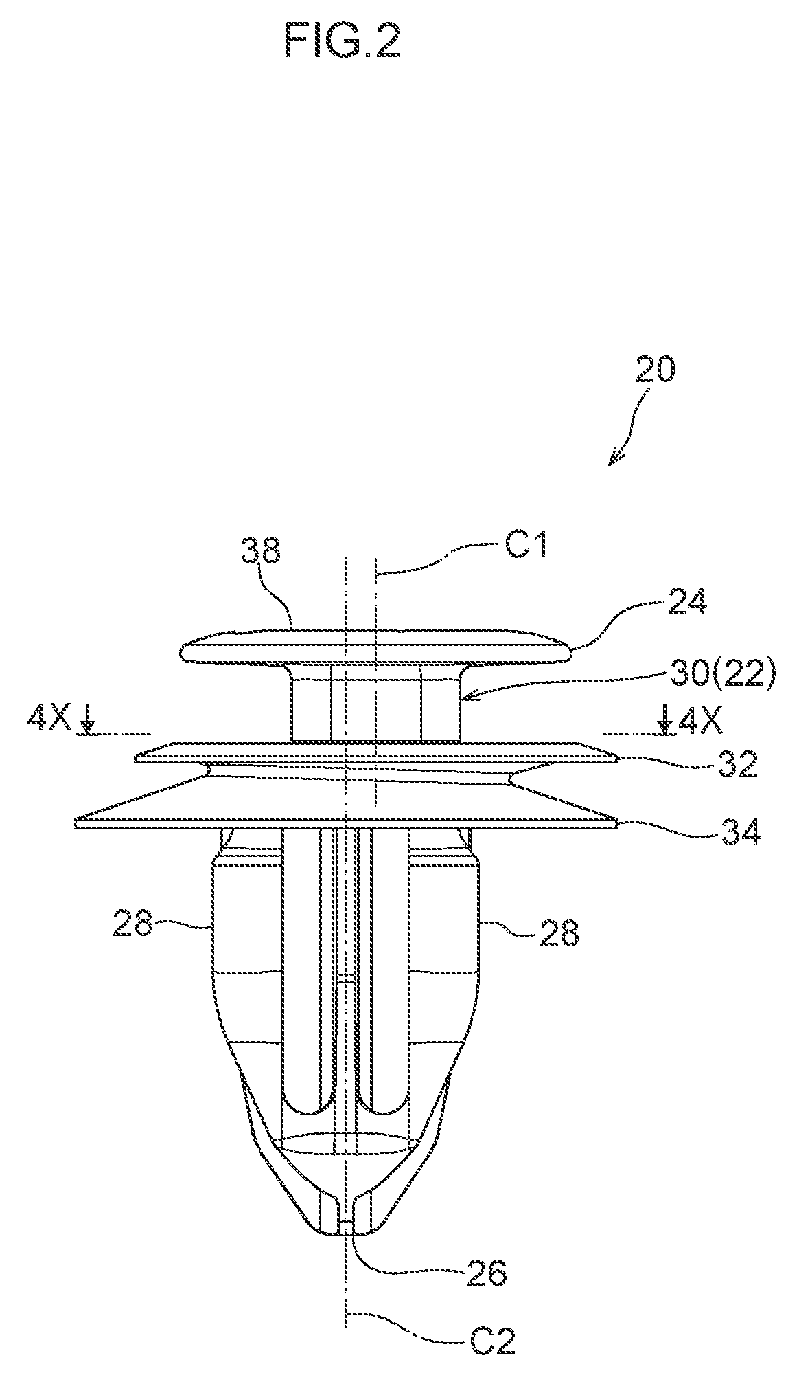
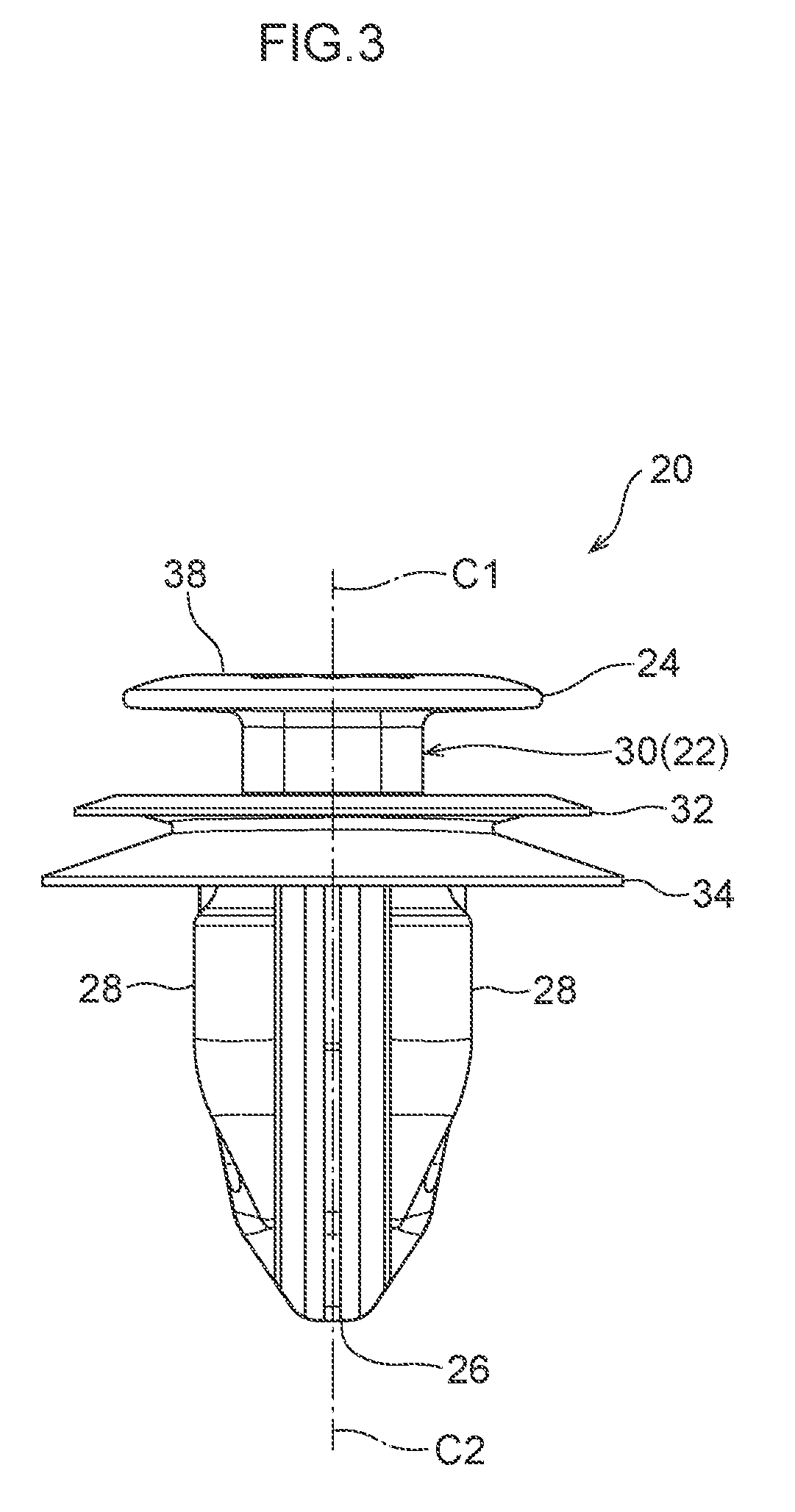
[0037]A mounting structure S relating to an embodiment of the present disclosure is described next by using FIG. 1 through FIG. 7. The mounting structure S of the present embodiment has a first member 12, a second member 16, and a clip 20.

[0038]As shown in FIG. 1 and FIG. 7, the first member 12 has a plate-shaped portion 12A. A through-hole 14 is formed in the plate-shaped portion 12A. The through-hole 14 is a long hole, and a length direction one end portion of the through-hole 14 is connected to a cut-out 15 that is formed in an edge portion of the first member 12. Opening width W1 of the cut-out 15 is narrower than minimum opening width W2 of the through-hole 14. Note that the through-hole 14 of the present embodiment is an example of the first through-hole in the present disclosure, and the minimum opening width W2 is an example of the minimum opening length in the present disclosure.[0039]Further, the first member 12 of the present embodiment is a trim member for a vehicle (e.g...


PUM


Abstract

A mounting structure has: a first member in which a first through-hole is formed; a second member in which a second through-hole is formed; and a clip having a first shaft portion, a first anchor portion that is anchored on an edge portion of the first through-hole, a second shaft portion whose axial center is eccentric with respect to an axial center of the first shaft portion, and a second anchor portion that is anchored on an edge portion of the second through-hole, wherein a cross-sectional shape of a portion, which is disposed at an inner side of the first-through hole, of the first shaft portion is a polygonal shape, and a length along a longest diagonal line of the polygonal shape, or a length of a longest side of the polygonal shape, is longer than a minimum opening length of the first through-hole.

Description

CROSS-REFERENCE TO RELATED APPLICATION[0001]This application is based on and claims priority under 35 USC 119 from Japanese Patent Application No. 2018-049725 filed on Mar. 16, 2018, the disclosure of which is incorporated by reference herein.BACKGROUNDTechnical Field[0002]The present invention relates to a mounting structure and a clip.Related Art[0003]A clip in which the axial center of a second shaft portion is eccentric with respect to the axial center for a first shaft portion is disclosed in Japanese Patent No. 5613525. In this clip, because the axial center of the first shaft portion and the axial center of the second shaft portion are eccentric with respect to one another, mounting of a first member and a second member is possible even if there is relative positional offset between a first mounting hole of the first member, in which the first shaft portion is inserted, and a second mounting hole of the second member in which the second shaft portion is inserted.[0004]By the ...

Claims


Application Information

Patent Timeline
IPC IPC(8): F16B19/00F16B21/06F16B21/18F16B13/06
CPCF16B21/06F16B21/183F16B13/061F16B19/004F16B19/002F16B21/086F16B5/065F16B5/0657F16B21/09F16B21/02F16B5/0628F16B21/082
Inventor ITO, NOBUYUKIINAGAKI, YUYA
Owner NIFCO INC
Why Eureka
Try Eureka