Valve timing control apparatus and internal combustion engine

Inactive Publication Date: 2006-11-23
HITACHI LTD
View PDF3 Cites 5 Cited by
  • Summary
  • Abstract
  • Description
  • Claims
  • Application Information

AI Technical Summary

Benefits of technology

[0003] In the valve timing control apparatus of this document, the lock pin receives tow different hydraulic pressures at the two different pressure receiving portions. Therefore, it is difficult to minutely adjust the spring force of a spring biasing the lock pin to the lock position.
[0004] According to one aspect of the present invention, a valve timing control apparatus for an internal combustion engine, comprises: a driving rotary member adapted to be driven by the engine; a driven rotary member arranged to rotate relative to the driving rotary member and adapted to rotate a camshaft of the engine; a first movable member provided in a first rotary member, and arranged to move forwards and backwards, the first rotary member being one of the driving rotary member and the driven rotary member; and a second movable member provided in a second rotary member and arranged to move forwards and backwards, the second rotary member being the other of the driving rotary member and the driven rotary member. The first and second movable members are arranged to limit a relative rotation between the driving rotary member and the driven rotary member when both the first movable member and the second movable member are moved forwards, and to allow the relative rotation between the dri

Problems solved by technology

Therefore, it is difficult to minutely adjust the spring f

Method used


Image

  • Valve timing control apparatus and internal combustion engine
  • Valve timing control apparatus and internal combustion engine
  • Valve timing control apparatus and internal combustion engine

Examples


first embodiment

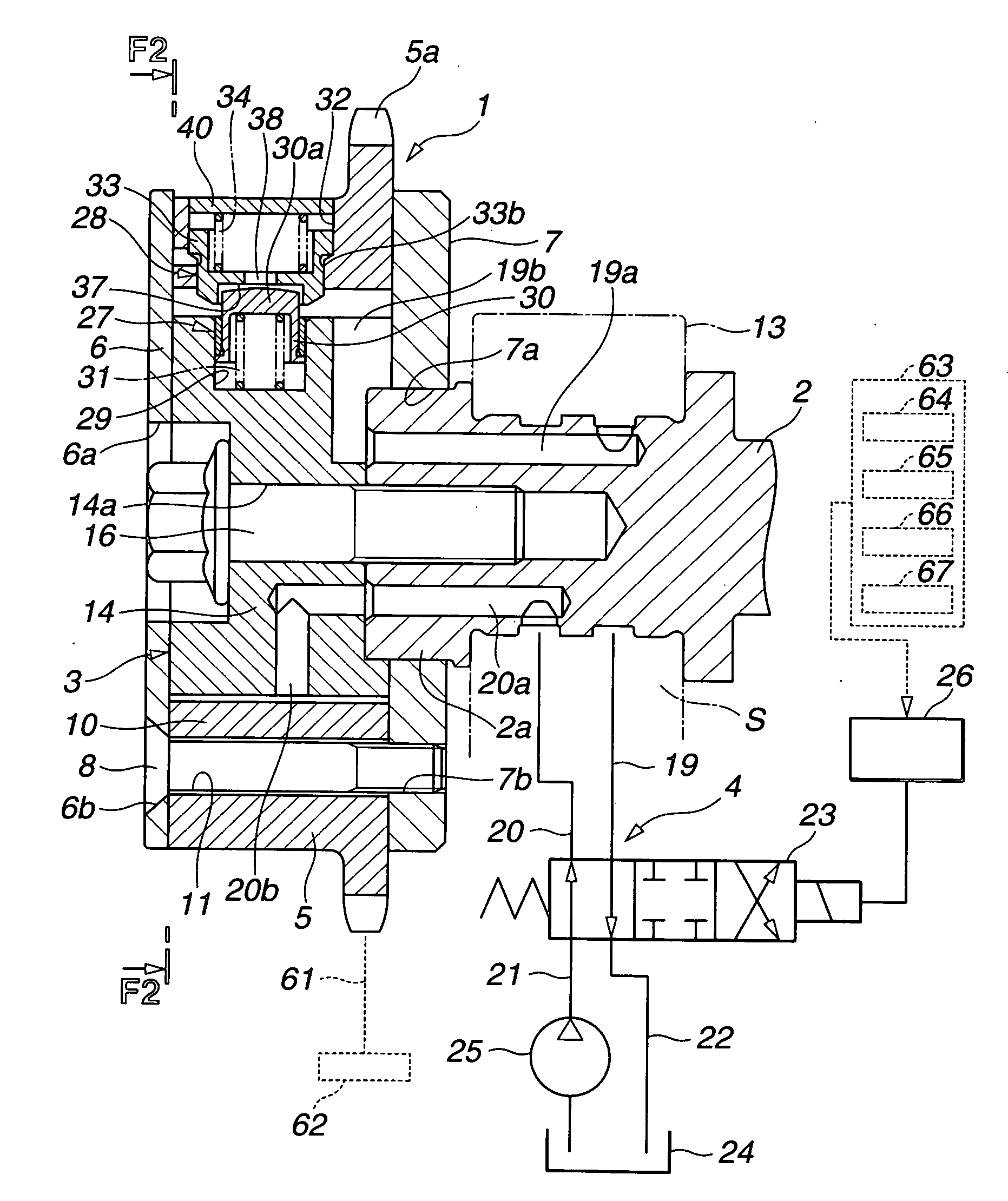
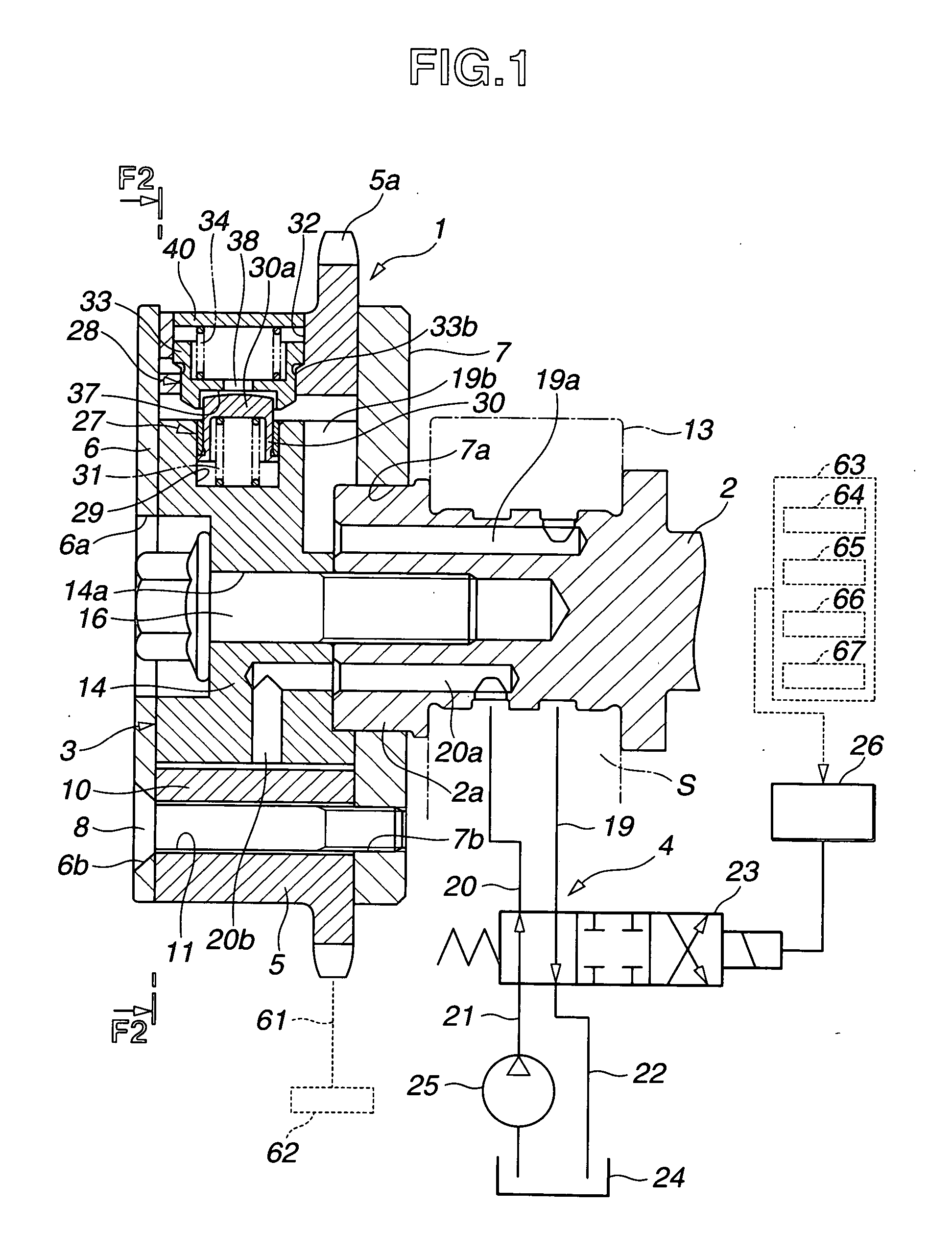
[0023]FIG. 1 shows an internal combustion engine equipped with a valve timing control apparatus or system according to the present invention. FIG. 2 shows the valve timing control apparatus in section taken across a line F2-F2 in FIG. 1 whereas FIG. 1 is a sectional view taken across a line F1-F1 shown in FIG. 2. In this embodiment, the present invention is applied to an intake valve's side. However, it is possible to apply the invention to an exhaust valve's side.

[0024] A timing sprocket member 1 is a driving rotary member driven through a timing chain 61 by a crankshaft 62 of the internal combustion engine. A camshaft 2 is rotatable relative to sprocket member 1. A vane member 3 is a driven rotary member which is fixed at an end of camshaft 2 so that they rotate as a unit, and which is encased rotatably in sprocket member 1. A hydraulic circuit 4 is a component of a control section to rotate vane member 3 in a forward rotational direction and a reverse rotational direction in spro...

second embodiment

[0079] FIGS. 7˜10 show a valve timing control apparatus according to the present invention. In the second embodiment, second lock member 33 is arranged to move backwards against the spring force of second spring 34 by the effect of a centrifugal force, instead of the hydraulic pressure in retard chambers 18. The spring force of second spring 34 is set smaller than a centrifugal force of a predetermined magnitude produced in housing 5 during rotation. In this example, second spring 34 is so set that second spring 34 starts compression by the centrifugal force of housing 5 when the engine rotational speed becomes equal to or higher than an idle speed of about 900 rpm.

[0080] An air release passage 41 is formed in the circumferential wall of housing 5 of sprocket member 1. Air release passage 41 connects the annular pressure chamber 33b with the outside, and thereby opens the inside of the annular pressure chamber 33a to the atmosphere to allow free movement of second lock member 33 in ...

third embodiment

[0088] With the circuit section including second control valve 43 for controlling the fluid pressure in the pressure chamber 33b independently from the fluid pressures in the advance and retard chambers 17 and 18, the valve timing control system can move the second lock member 33 forwards and backwards quickly by supplying and draining the hydraulic pressure directly to and from the pressure chamber 33b. Thus, the locking and unlocking operations of first and second lock members 30 and 33 are quick, and the response in the valve timing control is improved.

[0089] FIGS. 12˜15 show a valve timing control apparatus or system according to a fourth embodiment of the present invention. In the fourth embodiment, the first and second lock members 30 and 33 are in the form of a pin. In this embodiment, the first and second lock members or lock pins 30 and 33 are identical in size and shape. Each of first and second lock pins 30 and 33 includes a flange or slide portion 30c or 33c formed inte...


PUM


Abstract

A valve timing control apparatus includes a driving rotary member driven by an engine, and a driven rotary member to drive a camshaft of the engine. The driven member is rotatable relative to the driving rotary member. A first movable member is provided in one of the rotary members, and arranged to move forwards and backwards. A second movable member is provided in the other of the rotary members, and arranged to move forwards and backwards. The first and second movable members are arranged to limit a relative rotation between the driving rotary member and the driven rotary member when both the first movable member and the second movable member are moved forwards, and to allow the relative rotation when at least one of the first and second movable members is moved backwards.

Description

BACKGROUND OF THE INVENTION [0001] The present invention relates to an internal combustion engine equipped with a valve timing control apparatus and / or a valve timing control apparatus for controlling a valve timing of an internal combustion engine such as opening and closing timings of intake or exhaust valve. [0002] A published Japanese Patent Specification Publication No. 2000-002104 shows a valve timing control apparatus (VTC) of a vane type including a rotary unit of a timing sprocket member and a vane member, and a lock mechanism including a lock pin to limit a relative rotation between the timing sprocket member and vane member. The lock pin includes a small diameter pressure receiving section and a large diameter pressure receiving portion. SUMMARY OF THE INVENTION [0003] In the valve timing control apparatus of this document, the lock pin receives tow different hydraulic pressures at the two different pressure receiving portions. Therefore, it is difficult to minutely adjus...

Claims


Application Information

Patent Timeline
IPC IPC(8): F01L1/34
CPCF01L1/022F01L1/024F01L2001/34473F01L2001/34459F01L2001/34469F01L1/3442
Inventor SUGA, SEIJIYOSHIDA, HIDEKAZUTSUKADA, TOMOYA
Owner HITACHI LTD
Why Eureka
Try Eureka