Ratchet wrench

Inactive Publication Date: 2016-12-29
LAI JIM
View PDF6 Cites 0 Cited by
  • Summary
  • Abstract
  • Description
  • Claims
  • Application Information

AI Technical Summary

Benefits of technology

[0016]Preferably, the installation hole has multiple curved recesses defined in the inner periphery thereof Each of the rings has mul

Problems solved by technology

Nevertheless, the soundless design may confuse the users who cannot positively know which direction is the driving direction.
However, the pawl is engaged with the teeth of t

Method used


Image

  • Ratchet wrench
  • Ratchet wrench
  • Ratchet wrench

Examples


first embodiment

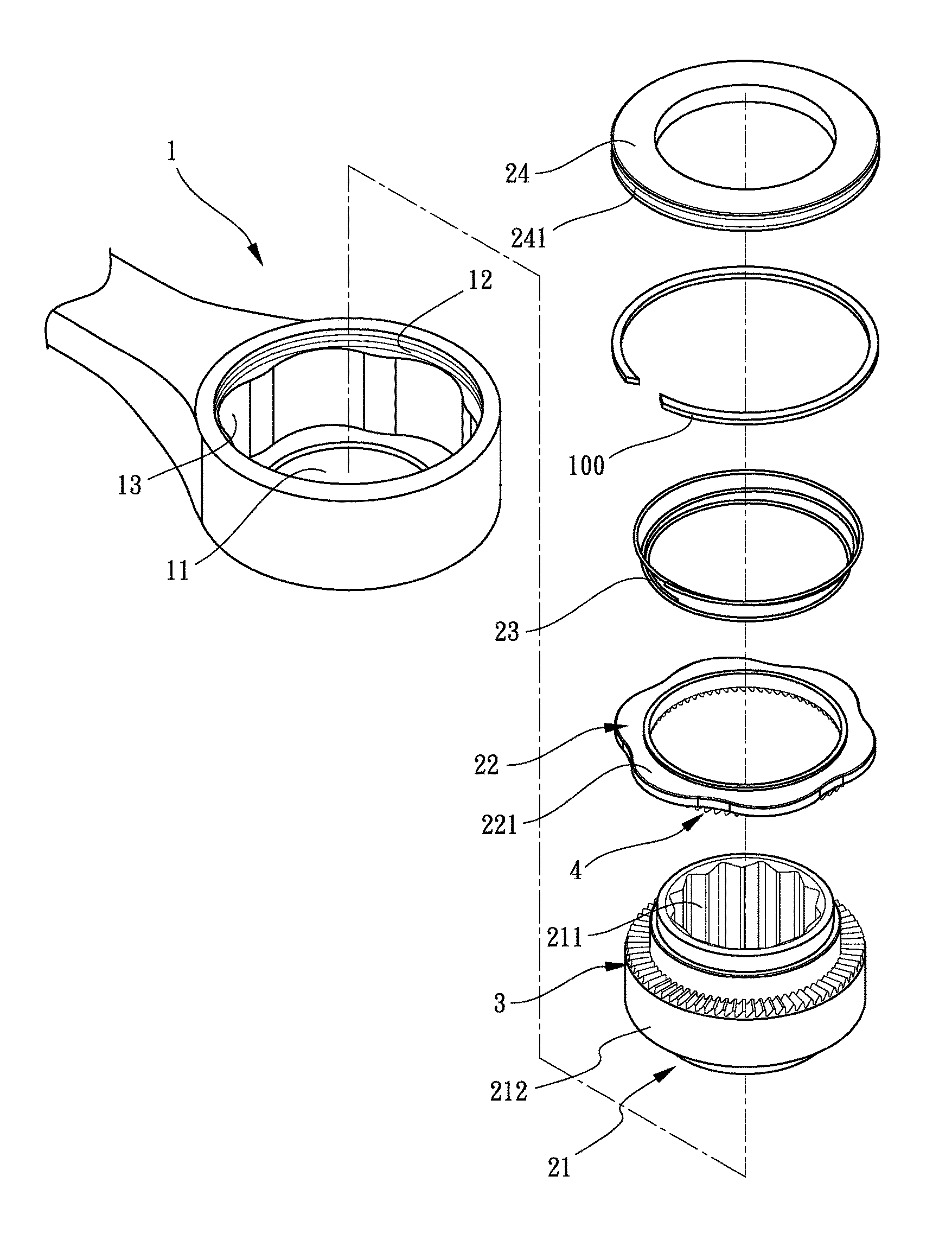
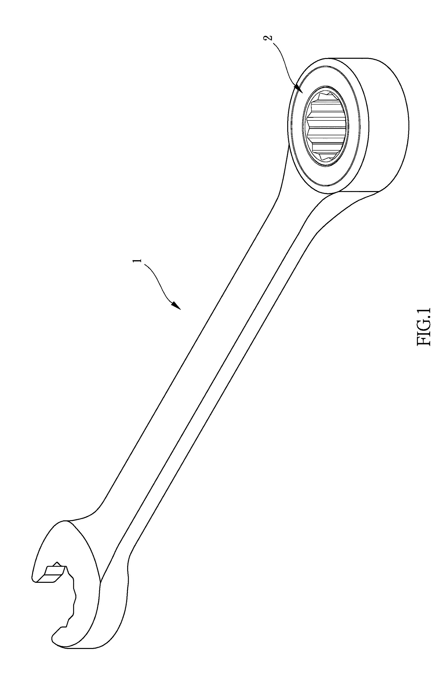
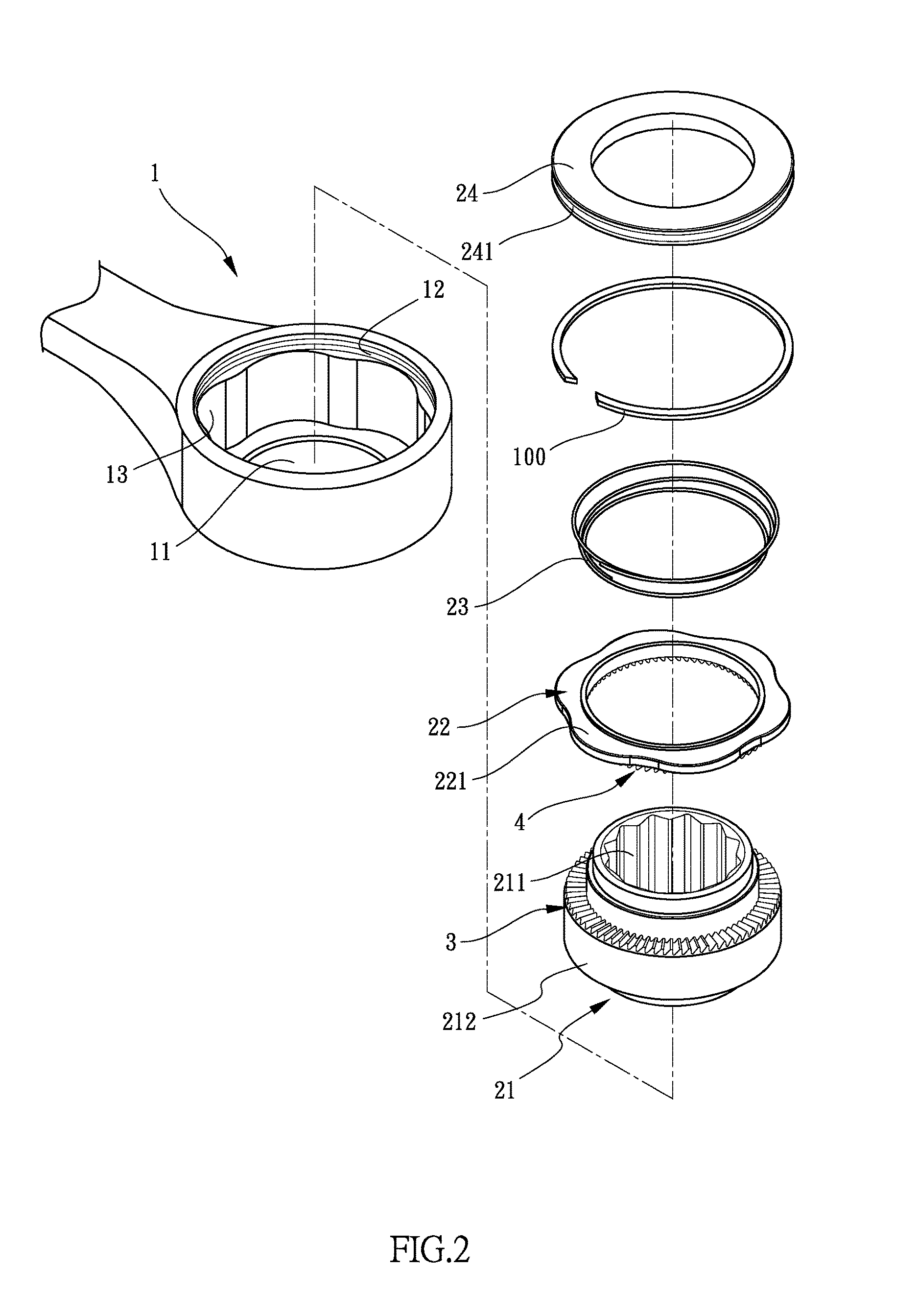
[0027]Referring to FIGS. 1 to 4, the ratchet wrench 1 of the present invention comprises a head having an installation hole 11 defined therethrough. A driving unit 2 is located in the installation hole 11 and has a ratchet seat 21, a ring 22, a resilient member 23 and a cover 24. The ratchet seat 21 has a driving hole 211 defined through the top and the bottom thereof Multiple first teeth 3 are defined in one of the top and the bottom of the outer periphery 212 of the ratchet seat 21. The ring 2 is mounted to the ratchet seat 21 and has second teeth 4 which are engaged with the first teeth 3 of the ratchet seat 21. The cover 34 is mounted to the ratchet seat 21 and located corresponding to the ring 22. The cover 34 seals the installation hole 11 in one of two sides of the head. The resilient member 23 is biased between the cover 24 and the ring 22 so as to resiliently push the second teeth 4 of the ring 22 to be engaged with the first teeth 3 of the outer periphery 212 of the ratche...

second embodiment

[0028]As shown in FIGS. 5 to 7, the present invention is disclosed, the ratchet wrench 1 comprises a head having an installation hole 11 defined therethrough. A driving unit 2 is located in the installation hole 11 and has a ratchet seat 5, two rings 22, two resilient members 7 and two covers 8. The ratchet seat 5 has a driving hole 51 defined through the top and the bottom thereof The shape of the driving hole 51 disclosed in FIG. 2 may vary according needs. The ratchet seat 5 has an outer periphery 52. Multiple first teeth 9 are defined in each of the top and the bottom of the outer periphery 52 of the ratchet seat 5. The two rings 2 are respectively mounted to the top and the bottom of the ratchet seat 5 and each have second teeth 10 which are engaged with the first teeth 9 of the ratchet seat 5 corresponding thereto. The two covers 34 are respectively mounted to the top and the bottom of the head ratchet seat 5 so as to seal the installation hole 11 in two sides of the head. Eac...


PUM


Abstract

A ratchet wrench includes a driving unit located in the installation hole of the head. The driving unit has a ratchet seat with a driving hole. Multiple first teeth are defined in one of the top and the bottom of the ratchet seat. A ring is mounted to the ratchet seat and has second teeth which are engaged with the first teeth of the ratchet seat. A cover is mounted to the ratchet seat and located corresponding to the ring. A resilient member is biased between the cover and the ring so as to resiliently push the second teeth of the ring to be engaged with the first teeth of the ratchet seat. The first teeth move over the second teeth to generate sound to acknowledge the user the driving direction.

Description

BACKGROUND OF THE INVENTION[0001]1. Fields of the invention[0002]The present invention relates to a ratchet wrench, and more particularly, to a ratchet wrench which acknowledges the user the driving direction by sound generated by teeth of one part moving over teeth of another part.[0003]2. Descriptions of Related Art[0004]The conventional ratchet wrenches usually comprises head in which a driving member is rotatably received. The driving member has teeth defined in the outer periphery thereof A pawl is movably received in a recess of the head of the ratchet and is controlled by a biasing unit which is controlled by a control lever. The user operates the control lever to activate the biasing unit to move the pawl in the recess so as to be engage with the driving member to output torque to an object that is engaged with the driving member. The users need to check the driving direction often by checking the position that the control lever, or to check the marks on the body of the wren...

Claims


Application Information

Patent Timeline
IPC IPC(8): B25B13/46B25B23/00
CPCB25B23/0007B25B13/462B25B13/466
Inventor LAI, JIM
Owner LAI JIM
Why Eureka
Try Eureka