Injection dart

Active Publication Date: 2015-12-10
PNEU DART
View PDF2 Cites 4 Cited by
  • Summary
  • Abstract
  • Description
  • Claims
  • Application Information

AI Technical Summary

Benefits of technology

The present invention solves problems with injection darts by using a flow control member with unique geometries and features. This ensures reliable and consistent results in a specialized environment where rapidly changing pressures can occur. The invention includes a flow rate restrictor positioned within the dart to facilitate medium to rapid injection rates. Overall, the invention allows for better control and regulation of the injection process during dart usage.

Problems solved by technology

Studies have concluded the rate of injection can and will disturb living tissue and in some instances result in partial injection due to the dart propelled away from its intended target as a result of the injection rate.

Method used


Image

  • Injection dart
  • Injection dart
  • Injection dart

Examples


Embodiment Construction

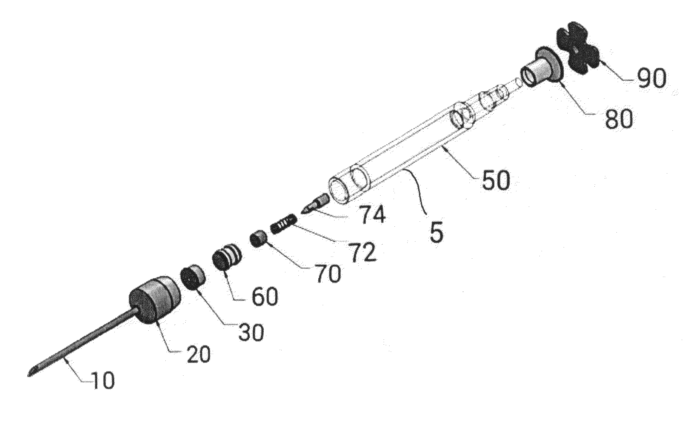
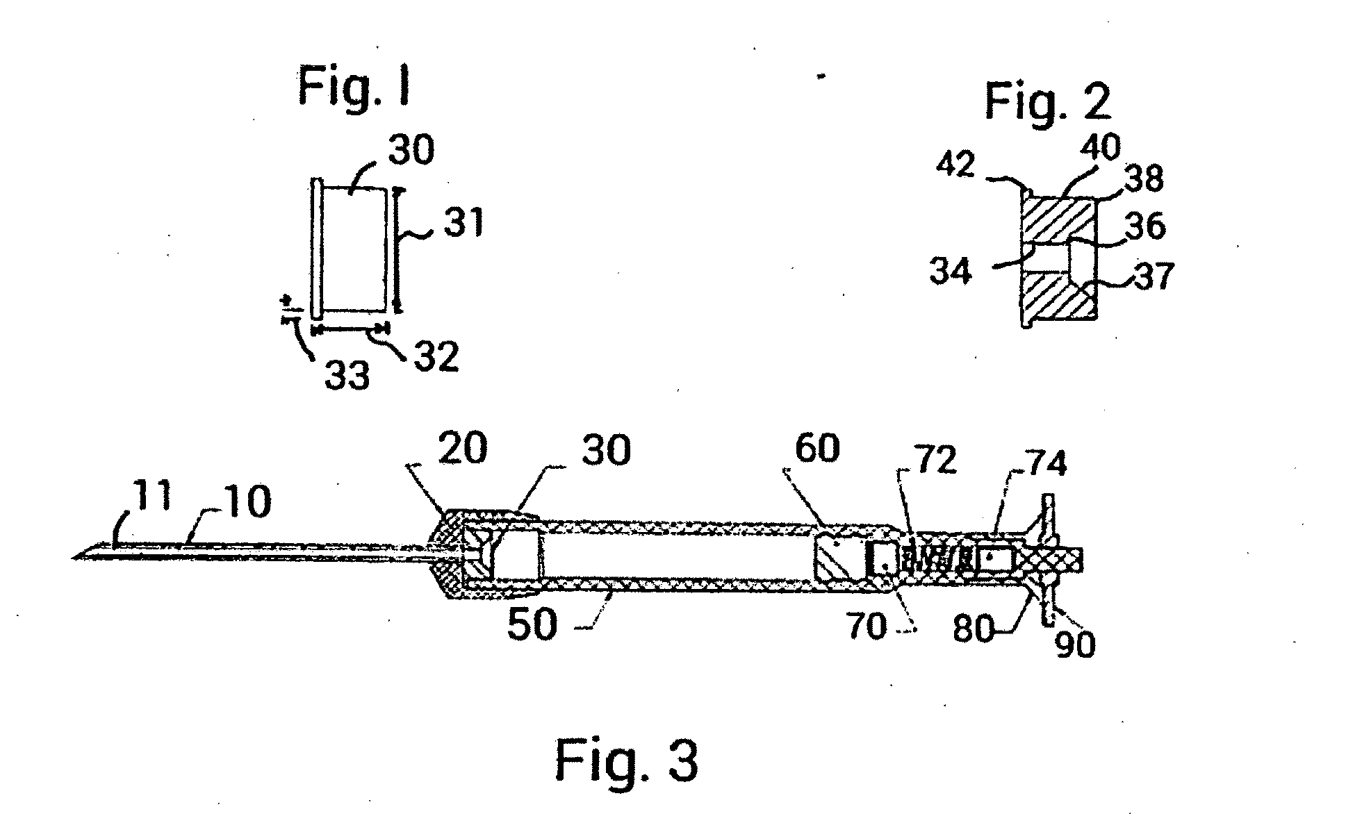
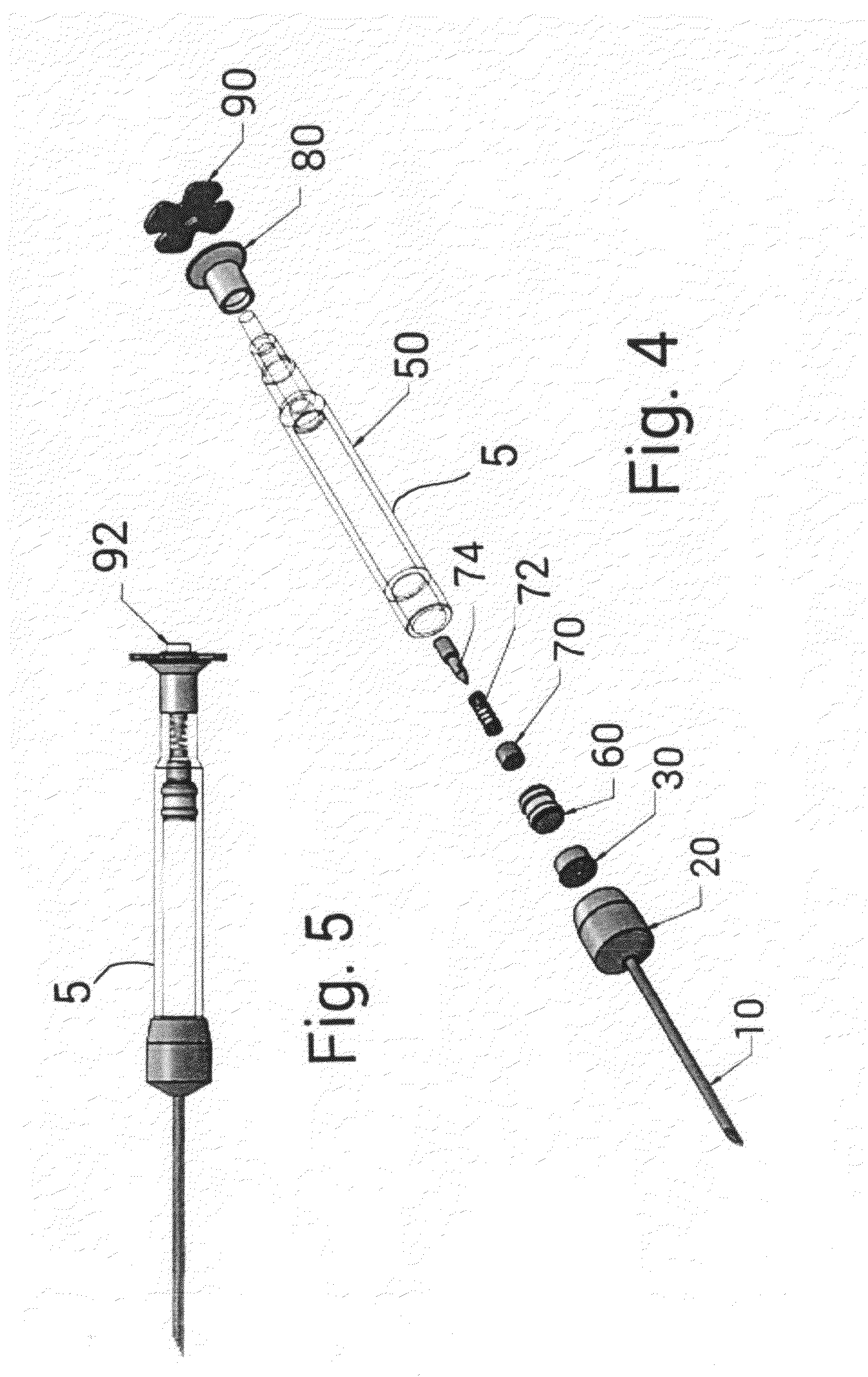
[0037]FIGS. 1, 2 and 6 show the details regarding the flow restrictor 30 of the present invention. An injection dart 5 into which the flow restrictor may be placed is shown in FIGS. 3, 4 and 5.

[0038]Referring to FIGS. 3, 4 and 5, the injection dart 5 (preferably approximately 4¾ inches long), includes a cannula (or injection needle) 10 at the dart's anterior or forward end. The cannula includes an inner bore 11 through which medications are injected into an animal. The cannula may also have an opening (not shown) along its cylindrical wall to allow for the passage of medications not only through the forward end of the inner bore 11 but also at a point along its length. The cannula 10 is aligned along and defines a centerline of the dart 5. The cannula 10 is firmly attached to the center of a ferrule 20. The ferrule 20 is a generally cylindrical cup shaped and has a closed forward end through with the cannula 10 extends and is preferably formed of aluminum or other light metal. The c...


PUM


Abstract

An improved injection dart is disclosed. A flow restrictor positioned at a forward end of a dart body is provided. The flow restrictor has a generally cylindrical restrictor body portion and a radially outward extending flange portion at a forward end thereof. The flange is securely held in position. The restrictor body also having a recess in a rearward end. The flange portion holds said restrictor in a position where an inner bore of a cannula is precisely aligned with the restrictor bore. The restrictor acts to diminish a variable flow rate so that all flow rates above a maximum flow rate are restricted to be less than the maximum flow rate. The flange also keeps a forward end of the flow channel bore open but allows for radially inward deformation of the restrictor at a rear end of said flow channel bore.

Description

BACKGROUND OF THE INVENTION[0001]1. Field of the Invention[0002]The present invention relates to an improved injection dart. More specifically, it relates to an improved injection dart which employs a flow restrictor which limits and controls the rate of flow of an injection administered by the dart.[0003]2. Description of the Prior Art[0004]Dart-type projectiles carrying a self-contained actuating means whereby detonate upon rapid deceleration are generally well known in delivering drugs, medicines and the like to animals from a distance. Studies have concluded the rate of injection can and will disturb living tissue and in some instances result in partial injection due to the dart propelled away from its intended target as a result of the injection rate. The use of hypodermic darts to administer anesthesia or other medications to animals is well known in the art. An early example is described and shown in Harris, U.S. Pat. No. 1,815,300. A number of injecting projectiles have been...

Claims


Application Information

Patent Timeline
IPC IPC(8): A61M5/20
CPCA61M5/2053A61M2005/2013F42B12/54A61M5/16813A61M5/16881A61M5/2033A61M5/3134A61M5/34
Inventor SOARS, BLAIR D.
Owner PNEU DART
Why Eureka
Try Eureka