Image Inspection Apparatus, Image Inspection Method, Image Inspection Program, Computer-Readable Recording Medium And Recording Device

a technology of image inspection and inspection method, which is applied in the direction of image enhancement, instruments, image data processing, etc., can solve the problems of inability to accurately detect information, deterioration in accuracy, and difficulty in stably performing inspection, so as to achieve sufficient accuracy and easy inspection of workpiece flaws and printed characters

Active Publication Date: 2015-12-10
KEYENCE
View PDF11 Cites 80 Cited by
  • Summary
  • Abstract
  • Description
  • Claims
  • Application Information

AI Technical Summary

Benefits of technology

[0011]The present invention has been made in view of such problems, and a principal object is to provide an image inspection apparatus, an image inspection method, an image inspection program, and a computer-readable recording medium or a recording device, each of which allows easier inspection of a flaw and a printed character of a workpiece while keeping sufficient accuracy in a practical use by a photometric stereo method.

Problems solved by technology

However, in such an image inspection apparatus, there has been a case where the viewing easiness varies by a type of illumination or a direction of applying illumination, depending on a type of the workpiece.
Further, in the conventional image inspection apparatus, erroneous inspection is apt to occur due to a small change in illumination condition, installation condition or the like, and stably performing inspection is difficult, which has been problematic.
Further, in visual inspection of the workpiece, although both information on a shape of the workpiece such as a flaw and an edge, i.e., three-dimensional information, and planar information such as a printed character and a stain are inspection targets, those information cannot be detected well in some cases as a result of interference of the information, which has also been problematic.
However, in the image inspection by the photometric stereo method, since accurate information of a positional relation between a light source and a workpiece is required for calculating an accurate normal vector, for example when the surface on which the workpiece is placed is inclined from a horizontal plane or illumination is inclined, a number of major changes occur to cause deterioration in accuracy, which has been problematic.
Further, calculating an accurate normal vector requires a great number of images obtained by illumination in different directions, to take enormous amount of processing time, which has also been problematic.

Method used


Image

  • Image Inspection Apparatus, Image Inspection Method, Image Inspection Program, Computer-Readable Recording Medium And Recording Device
  • Image Inspection Apparatus, Image Inspection Method, Image Inspection Program, Computer-Readable Recording Medium And Recording Device
  • Image Inspection Apparatus, Image Inspection Method, Image Inspection Program, Computer-Readable Recording Medium And Recording Device

Examples


first example

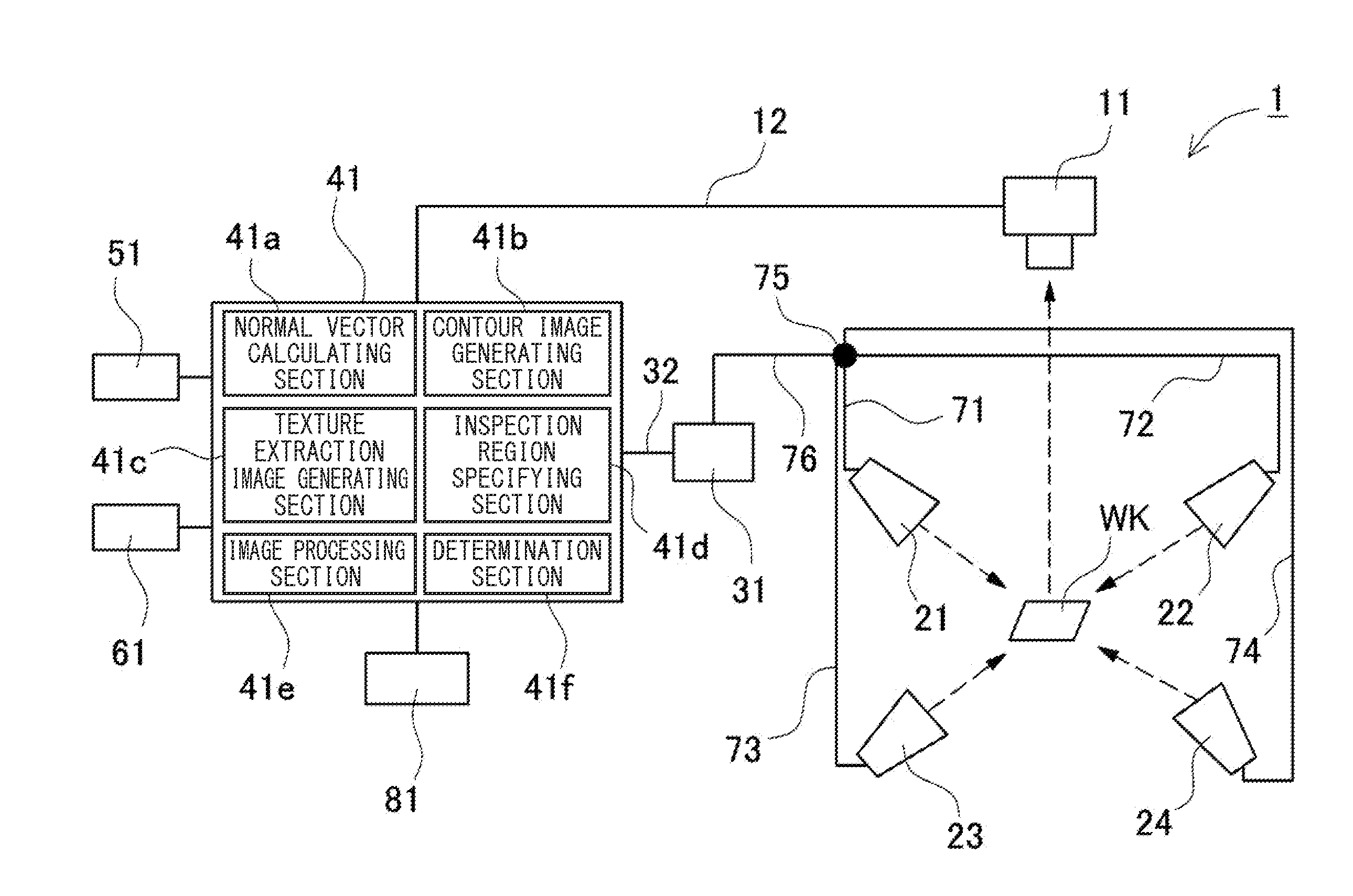
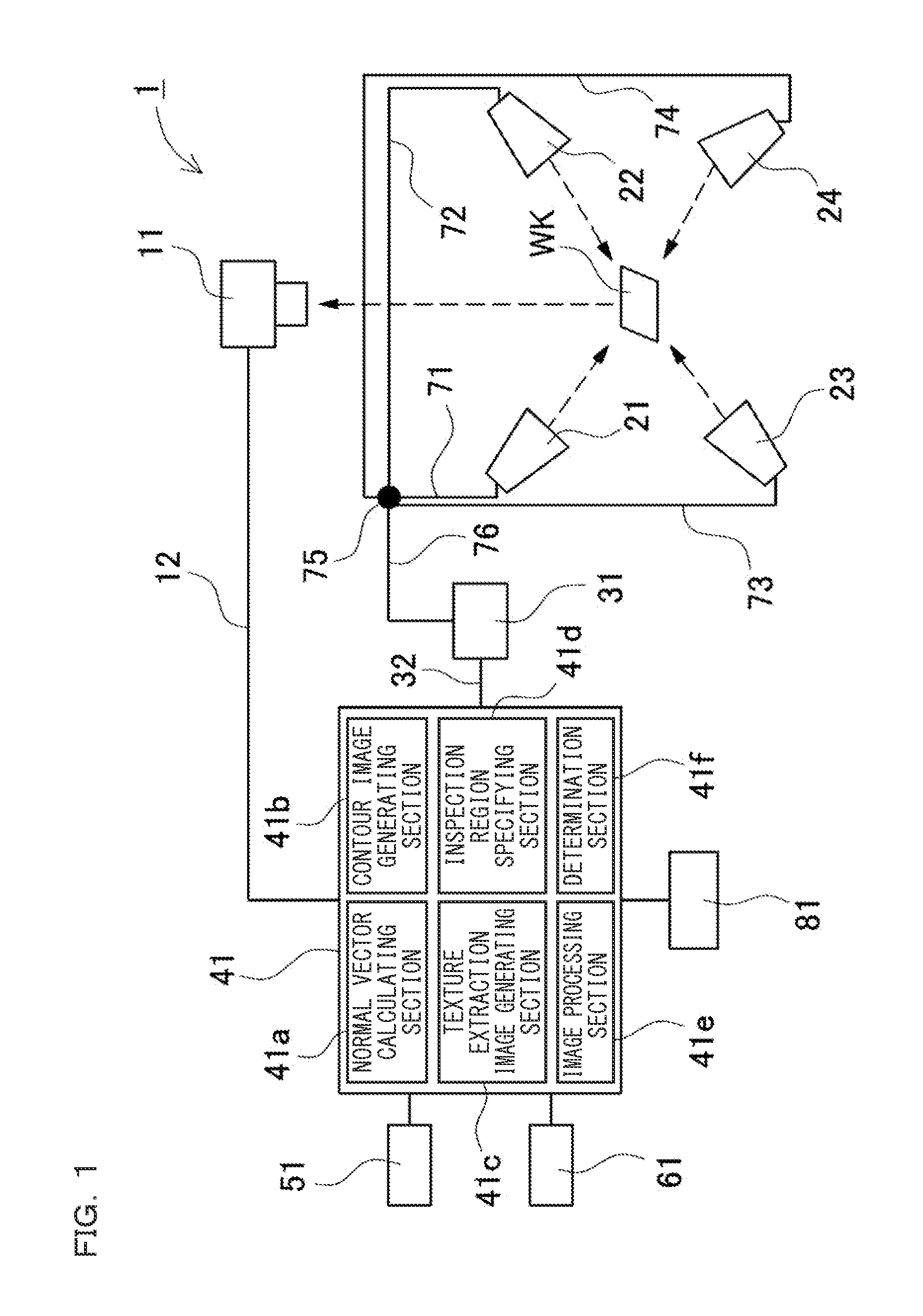
[0161]FIG. 24 shows a state where a first illumination cable 71, a second illumination cable 72, a third illumination cable 73 and a fourth illumination cable 74, which are respectively extended from the first illumination section 21, the second illumination section 22, the third illumination section 23 and the fourth illumination section 24 shown in FIG. 2, are connected to the illumination dividing unit. The illumination dividing unit is provided with an illumination connector for connecting each of the illumination cables. By connecting the illumination cable to each of the illumination connectors, electricity is supplied from the illumination controlling section 31 at predetermined turning-on timing, to allow turning-on of the illumination section. In this case, when the illumination cable is erroneously connected to an illumination connector different from the original, a partial illumination image is captured in a different illumination direction or at different illumination t...

second example

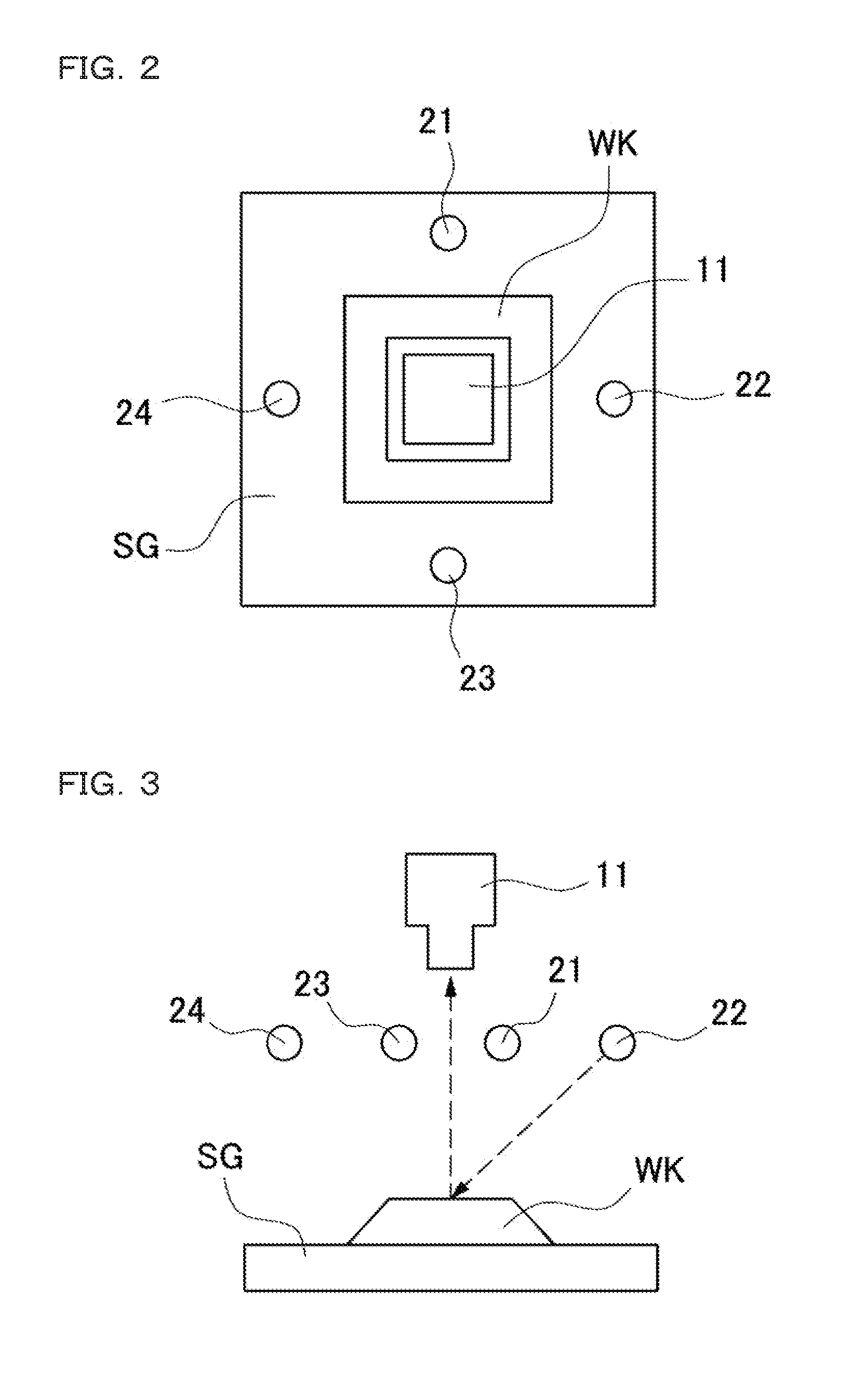
[0163]In the above example, there has been described the example of supporting the operation to wire each of the illumination sections to the illumination controlling section by the installation auxiliary section. In this case, the installation auxiliary section is provided on each of the illumination sections and the illumination cable. However, the installation auxiliary section is not restricted to this, and is applicable to supporting an operation of installing the illumination section at a correct position. In this case, the installation auxiliary section can be provided on each of the imaging section and the illumination section. Such an example is shown in a schematic plan view of FIG. 26. In this example, the first illumination section 21, the second illumination section 22, the third illumination section 23 and the fourth illumination section 24, each being formed in an arc shape, are arranged around (here, to the north, south, east and west of) the imaging section in a pla...

third example

[0166]In the above second example, there has been described the example where the relative installation positions at the time of annularly arranging three or more illumination sections around the workpiece are confirmed by the installation auxiliary section. The illumination sections can also be integrally configured in advance as an annular illumination unit as described above. Also in such a case, as shown in FIG. 23, unless the annular illumination unit 20 is fixed by adjusting its relative rotational position, namely rotational angle, with respect to the imaging section, an accurate result of the photometric stereo processing cannot be obtained. Especially when the annular illumination unit 20 has a point-symmetric shape, a rotational position is not decided, thus making the adjustment operation difficult. Even in such a case, the relative rotational positions of the annular illumination unit and the imaging section can be positioned by the installation auxiliary section. For ex...


PUM

PropertyMeasurementUnit
incident angleaaaaaaaaaa
roughnessaaaaaaaaaa
processingaaaaaaaaaa

Abstract

An image inspection apparatus includes: an imaging section for capturing an image of a workpiece from a certain direction; an illumination section for illuminating the workpiece from different directions at least three times; an illumination controlling section for sequentially turning on the illumination sections one by one; an imaging generating section for driving the imaging section to generate a plurality of images; a normal vector calculating section for calculating a normal vector with respect to the surface of the workpiece at each of pixels by use of a pixel value of each of pixels having a corresponding relation among the plurality of images; and a contour image generating section for performing differential processing in an X-direction and a Y-direction on the calculated normal vector at each of the pixels, to generate a contour image that shows a contour of inclination of the surface of the workpiece.

Description

CROSS-REFERENCE TO RELATED APPLICATIONS[0001]The present application claims foreign priority based on Japanese Patent Application No. 2014-119135, filed Jun. 9, 2014, the contents of which is incorporated herein by reference.BACKGROUND OF THE INVENTION[0002]1. Field of the Invention[0003]The present invention relates to an image inspection apparatus, an image inspection method, an image inspection program, and a computer-readable recording medium or a recording device, each using a photometric stereo method.[0004]2. Description of Related Art[0005]There has been used an image inspection apparatus for performing inspection of the presence or absence of a flaw on the surface of a workpiece (inspection target or subject), an external shape thereof, and reading of a printed character thereon. Such an image inspection apparatus performs necessary illumination on a workpiece, captures its image, and performs image processing such as edge detection on the obtained image data, to perform de...

Claims


Application Information

Patent Timeline
Patent Type & Authority Applications(United States)
IPC IPC(8): G01N21/88G06T7/00H04N13/02
CPCG01N21/8806H04N13/0207G06T2207/10152G01N2201/06G06T2207/30164G06T7/0004G06T7/586G01B11/24G01N21/8851H04N13/254H04N13/207G06T7/0008
Inventor SUN, ZHUOLI
Owner KEYENCE
Why Eureka
Try Eureka