
Vibration-sensing field unit

a vibration sensor and field unit technology, applied in the field of vibration sensor, can solve the problems of limiting the size and amount of components including power sources, combining sensors may create additional problems, and vibration sensors are limited by their mass

Active Publication Date: 2015-12-10
UPTIME SOLUTIONS LLC
View PDF8 Cites 27 Cited by
  • Summary
  • Abstract
  • Description
  • Claims
  • Application Information

AI Technical Summary

Benefits of technology

The present patent is about a vibration-sensing field unit that can be used to monitor machine parameters in industrial facilities. The field unit is designed to combine multiple sensors into a single device to increase functionality without requiring multiple devices. However, combining sensors can create issues, such as limited operational time and delays. The field unit is made up of a flexible base and a body that supports a mass, which allows for the accelerometer to sense higher resonance frequencies. This flexible material isolates the mass from the accelerometer, allowing for additional components to be added without affecting the accuracy of the accelerometer. The field unit can be used to monitor various machine parameters, such as temperature, vibration, stress, acceleration, velocity, pressure, liquid level, gas level, gas concentration, sound, electric field, speed, torque, displacement, and more. The flexible material of the body allows for the field unit to isolate the mass from the accelerometer, resulting in greater functionality and efficiency.

Problems solved by technology

However, combining sensors may create additional issues.
For example, vibration sensors are limited by their mass since larger masses have lower resonance frequencies.
Consequently, the mass of vibration sensor devices is often kept below a threshold, limiting the size and amount of components including power source.
This in turn limits the operational time of the sensor devices on a given battery charge, resulting in delays, transmission errors, sensor device failures, frequent battery replacement, inefficiencies, greater expense, and safety concerns.

Method used


Image

  • Vibration-sensing field unit
  • Vibration-sensing field unit
  • Vibration-sensing field unit

Examples


Embodiment Construction

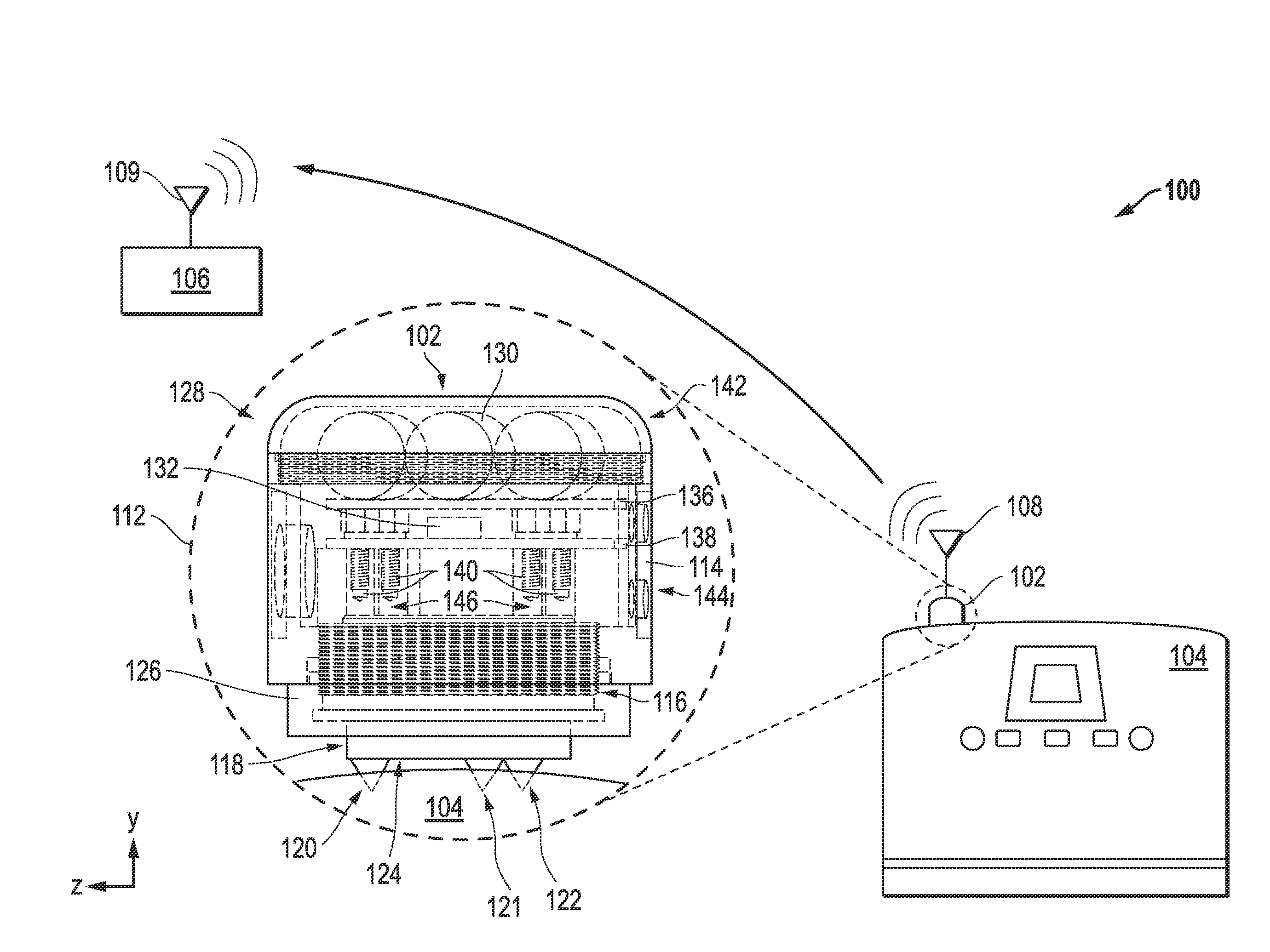
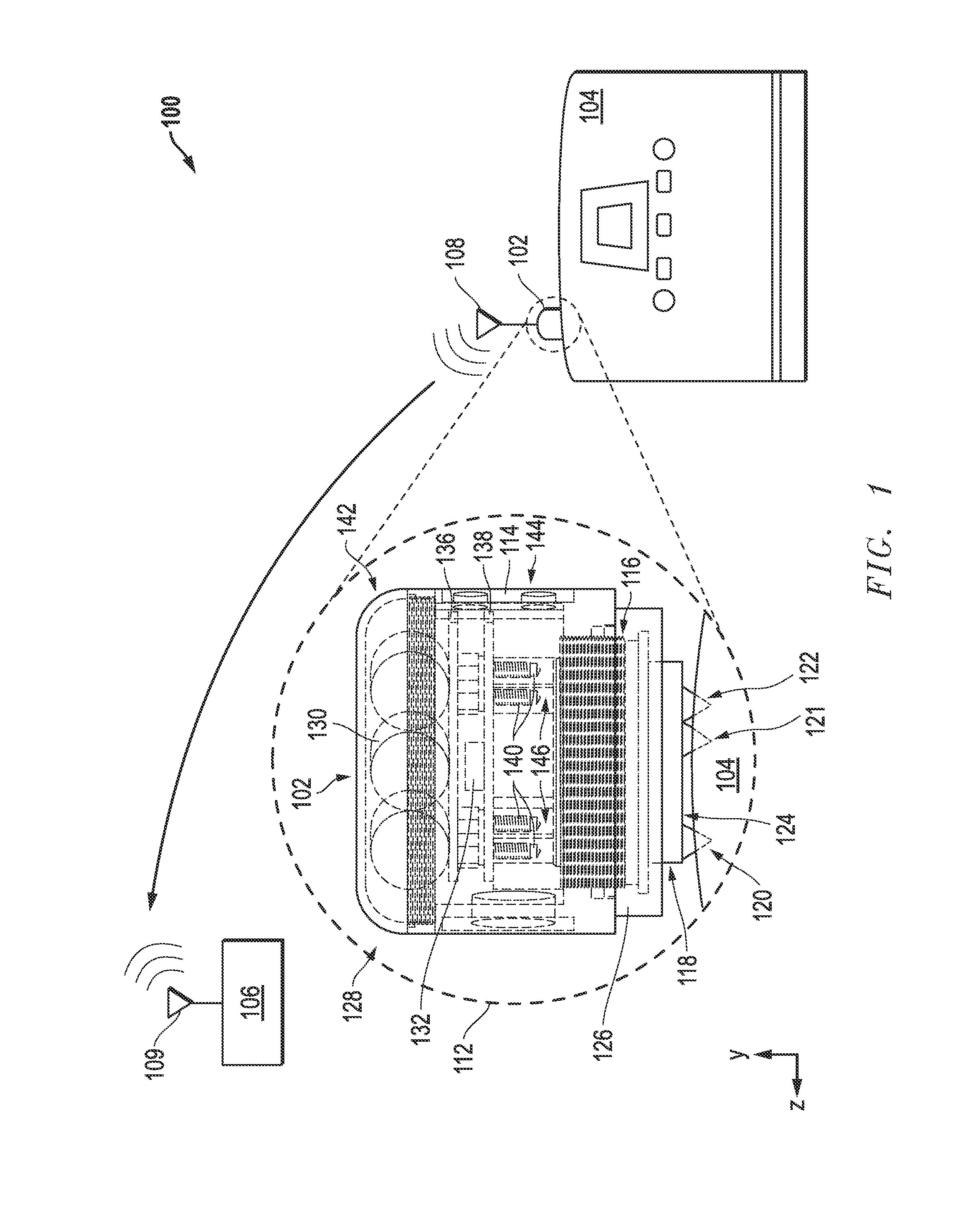
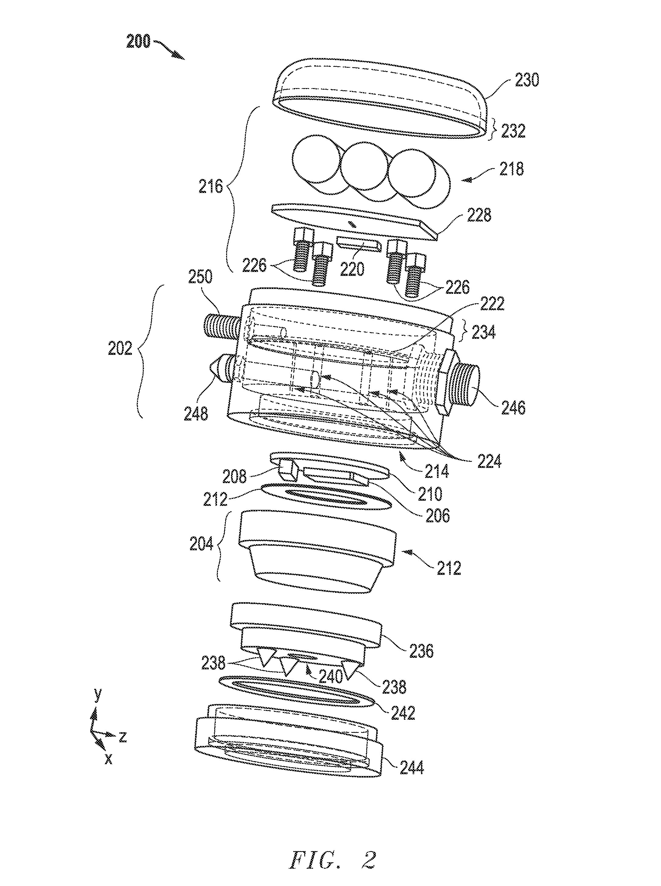
[0013]FIGS. 1-6 illustrate example implementations of a vibration-sensing field unit in accordance with some embodiments. The vibration-sensing field unit is used to monitor one or more machine parameters of at least one machine housed in a facility (which itself may be a machine). The machine parameters may include, for example, temperature, vibration, stress, acceleration, velocity, pressure, liquid level, gas level, gas concentration, sound, electric field, speed, torque, displacement, and any other information that may directly or indirectly indicate the status of a machine or a part of a machine, or an environment in which a machine is located.

[0014]The vibration-sensing field unit comprises a base comprising at least one accelerometer to sense vibrations, and a body mounted to the base. The body of the vibration-sensing field unit supports a mass, for example, a power supply, additional sensors, other electronics, and the like. The body is composed essentially of a flexible ma...


PUM


Abstract

A vibration-sensing field unit includes a base with at least one accelerometer, and a body mounted to the base. The base is composed essentially of a first material, while the body is composed essentially of a second material that is more flexible than the first material to reduce a vibration at the accelerometer caused by a mass supported by the body. In another embodiment, a vibration-sensing field unit includes at least one accelerometer and at least one ultrasonic transducer.

Description

CROSS-REFERENCE TO RELATED APPLICATION[0001]The present disclosure claims priority to U.S. Patent Application Ser. No. 62 / 010,008 (Attorney Docket No. 1005-UP003US-P), entitled “Vibration-Sensing Field Unit” and filed on Jun. 10, 2014, the entirety of which is incorporated by reference herein.BACKGROUND[0002]1. Field of the Disclosure[0003]The present disclosure relates generally to industrial facilities and, more particularly, to monitoring of machine parameters in industrial facilities.[0004]2. Description of the Related Art[0005]Industrial facilities, such as manufacturing facilities, laboratories, research facilities, refineries, other structures, and the like, often use sensors to monitor machine parameters. For example sensors may be used to measure machine parameters such as vibration, acceleration, velocity, sound, electric field, speed, torque, displacement, and the like. It is often desirable to combine multiple sensors into a single device to increase functionality withou...

Claims


Application Information

Patent Timeline
Patent Type & Authority Applications(United States)
IPC IPC(8): G01P15/097
CPCG01P15/097G01H1/00G01H11/08
Inventor GIRARDEAU, JAMES
Owner UPTIME SOLUTIONS LLC
Learn More