RFID tag

Active Publication Date: 2015-12-10
CRYOGATT SYST
View PDF12 Cites 16 Cited by
  • Summary
  • Abstract
  • Description
  • Claims
  • Application Information

AI Technical Summary

Benefits of technology

[0065]The intermediate structure (such as a jacket) may be attached to cryogenic vials that may or may not have their own tubular base portion thereby providing a means for the RFID tag to be quickly and easily be fitted or retrofitted to label the cryogenic vial.
[0066]The method of labelling a freestanding cryogeni

Problems solved by technology

The resulting encapsulated connection is strong and reduces the likelihood of a connectio

Method used


Image

  • RFID tag
  • RFID tag
  • RFID tag

Examples


Embodiment Construction

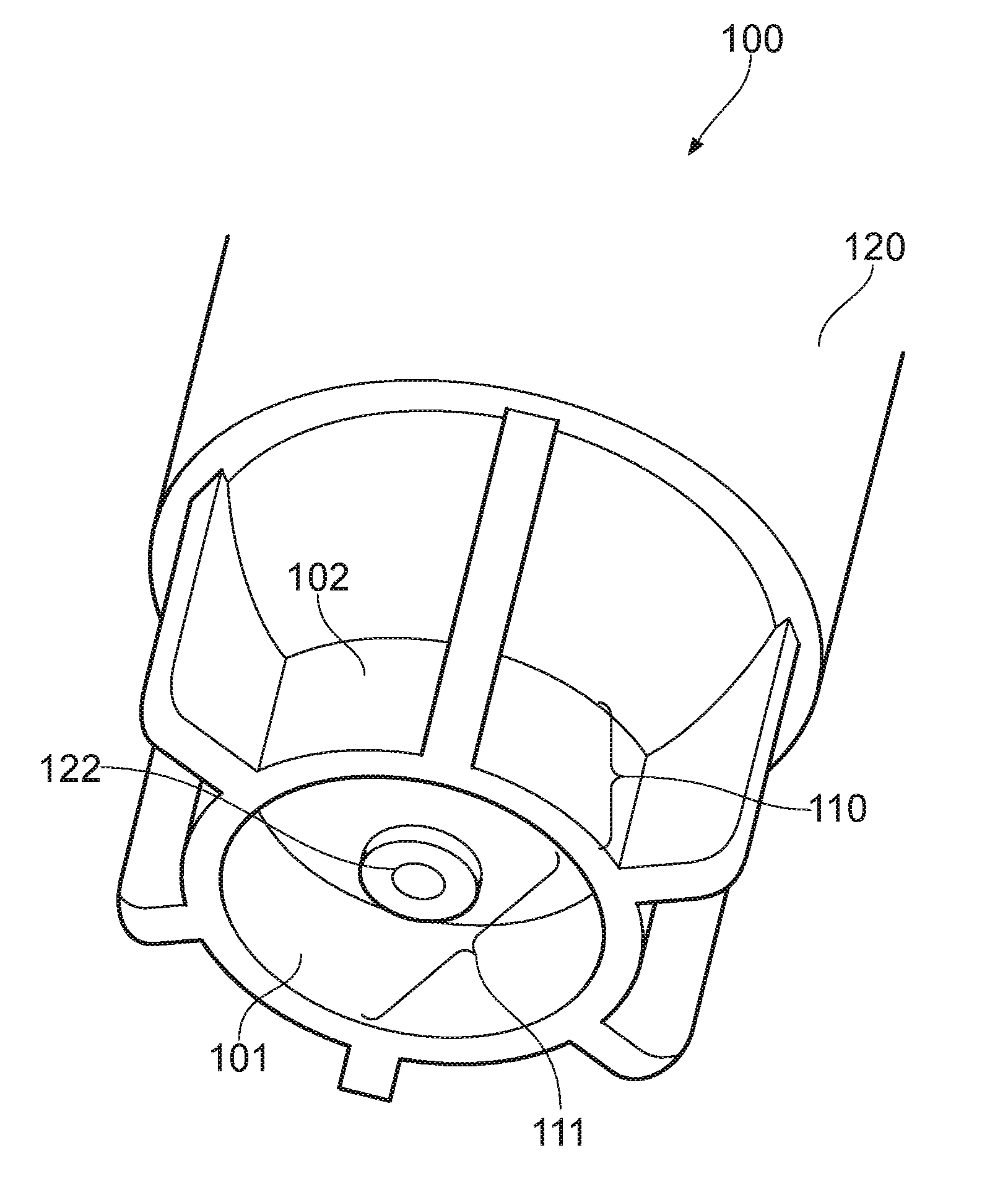
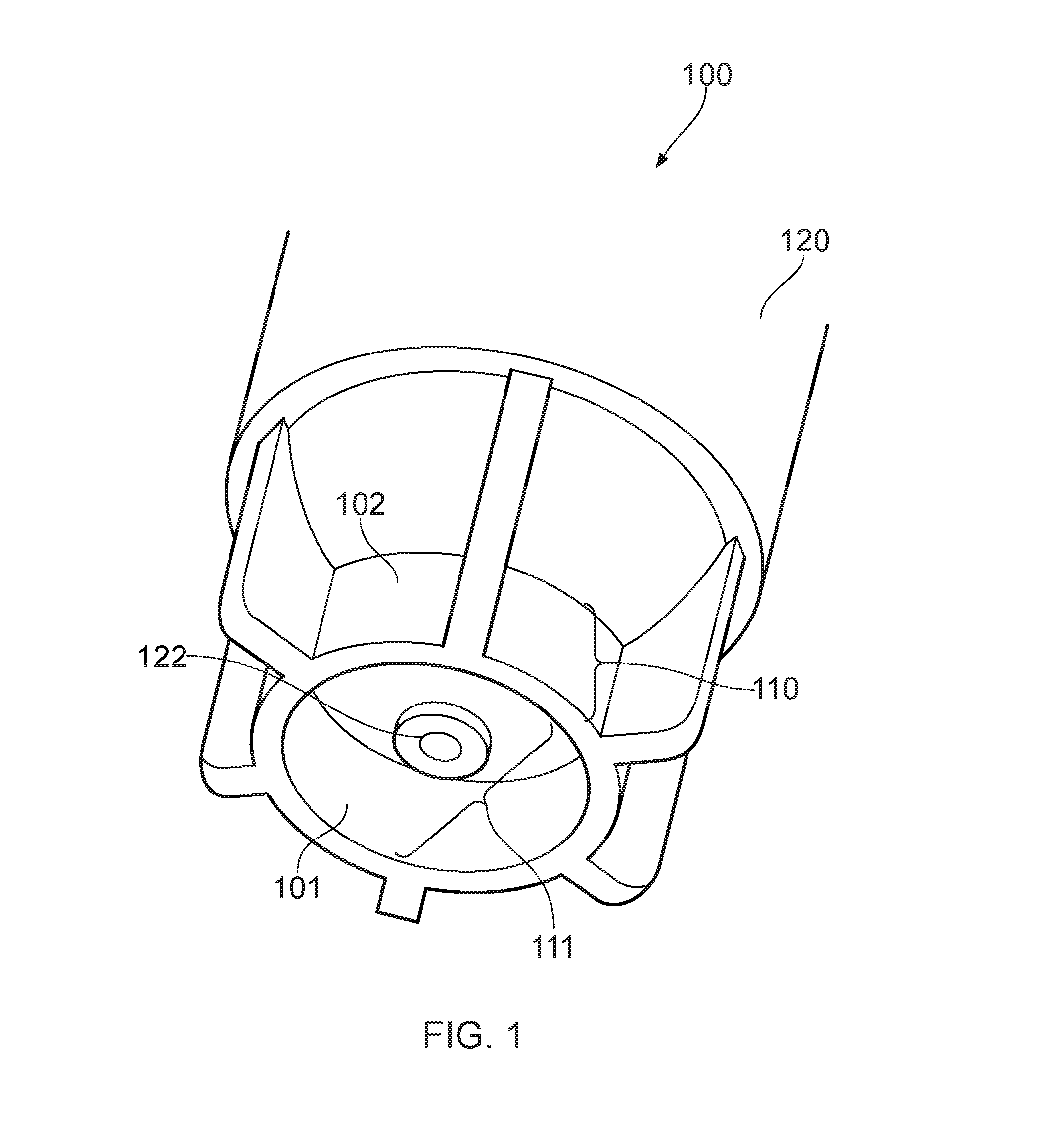
[0085]FIG. 1 shows a part of a freestanding cryogenic vial 100 having a tubular base portion 110 and a sample cavity 120. The tubular base portion 110 forms a tubular base cavity 111 which is separate from the sample cavity 120.

[0086]In order to facilitate sample retrieval, the sample cavity has a rounded bottom 122 which protrudes into the cavity 111 of the tubular base portion 110. The tubular base portion 110 has an external surface 102 and an internal surface 101 which, along with the bottom 122 of the sample cavity, defines the size and shape of the tubular base cavity 111.

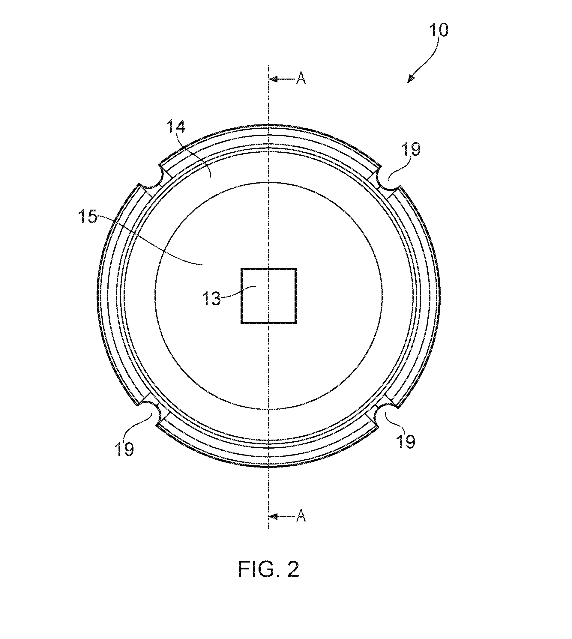
[0087]FIG. 2 shows a plan view of an RFID tag 10 for location inside the tubular base portion 110 of the freestanding cryogenic vial 100 of FIG. 1. FIG. 3 shows a cross-sectional view of the same RFID tag 10 taken along section A-A (shown in FIG. 2) and FIG. 4 shows a side view of the same RFID tag 10.

[0088]Referring to FIGS. 2-4, the RFID tag 10 includes an RFID chip 13, an antenna 14 connected to the chip 1...


PUM

PropertyMeasurementUnit
Temperatureaaaaaaaaaa
Temperature coefficient of resistanceaaaaaaaaaa
Structureaaaaaaaaaa

Abstract

An RFID tag for location inside a tubular base portion of a freestanding cryogenic vial, the RFID tag comprising: an RFID chip; an antenna connected to the chip; a support medium configured to support the chip and connected antenna; and a plug at least partially surrounding the chip, the antenna and the support medium, the plug being shaped to engage the tubular base portion of the vial. The RFID tag may be used to retrofit vials already stored at cryogenic temperatures.

Description

TECHNICAL FIELD [0001]The present invention relates to an RFID tag for location inside a tubular base portion of a freestanding cryogenic vial.BACKGROUND [0002]Biological samples may be preserved by cryogenic freezing. The biological samples are usually stored in disposable containers (disposables). The type of disposable container used depends on the type of sample. Examples of commonly used disposable containers include vials, straws and bags. The disposable container is stored at low temperatures in a Dewar flask typically filled with liquid nitrogen at a temperature of −196° C.[0003]Vials are generally tubular in shape, with a tubular wall defining a main longitudinal cavity (the sample cavity) for storage of the sample. The sample cavity can be sealed by a lid. Freestanding cryogenic vials include a base portion below the sample cavity which enables the vial to stand upright without the need for a support rack. The base portion of a freestanding vial is usually tubular in shape...

Claims


Application Information

Patent Timeline
IPC IPC(8): G06K19/077B01L3/00G06K19/08
CPCG06K19/07758G06K19/08Y10T29/4902B01L3/00G06K19/0772B01L3/545G06K19/041G06K19/07749B01L2300/022B01L2300/0851B01L3/5082B01L3/5453B01L2300/0832G06K19/06037G06K19/07775
Inventor MORRIS, GEOFFREY
Owner CRYOGATT SYST
Why Eureka
Try Eureka