

Monitoring System
a monitoring system and state monitoring technology, applied in the direction of alarms, instruments, etc., can solve the problems of increasing the risk of people not being able to notice the deterioration in the health of the elderly, the degradation of the living function of the elderly, and the inability of the elderly to move,
- Summary
- Abstract
- Description
- Claims
- Application Information
AI Technical Summary
Benefits of technology
Problems solved by technology
Method used
Image

Examples
first embodiment
Configuration of Monitoring System
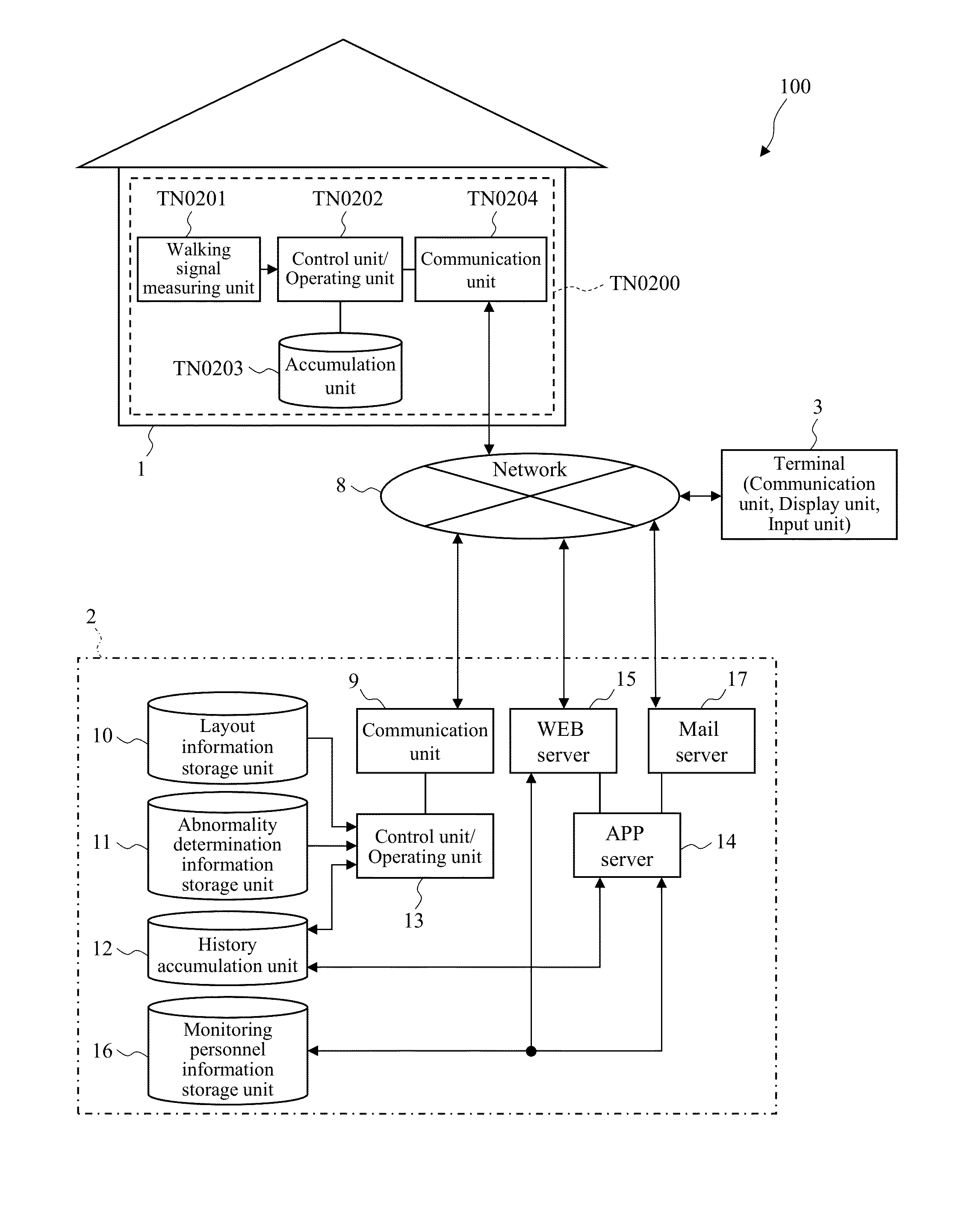
[0049]FIG. 1 shows an overall configuration diagram of a monitoring system according to a first embodiment of the present invention. The monitoring system 100 is provided with three major constituent elements. These are a facility 1 in which a monitoring subject (subject) resides or stays; an information processing system 2 that provides a monitoring service; and a terminal 3 utilized by monitoring personnel.
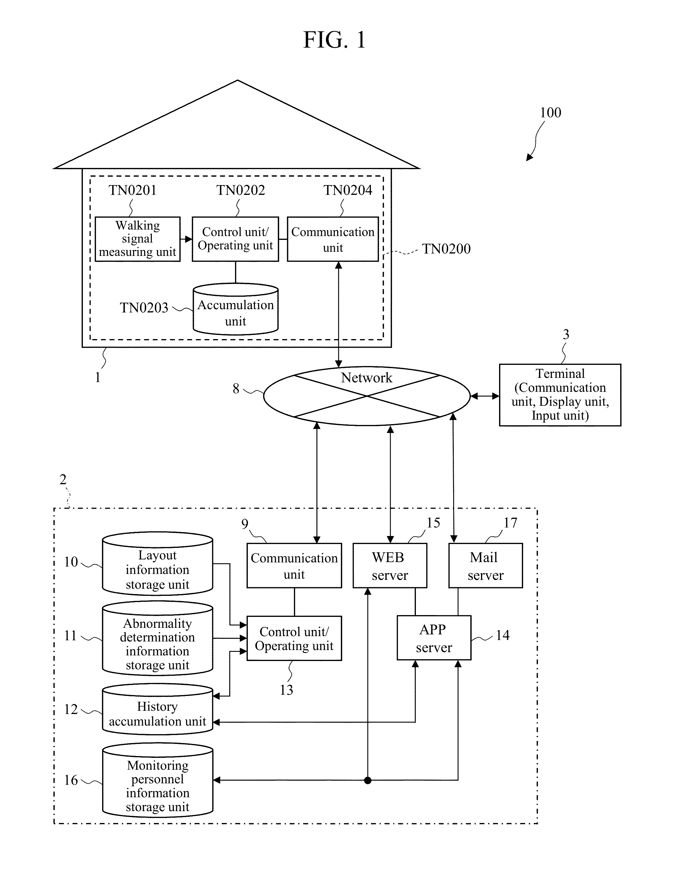
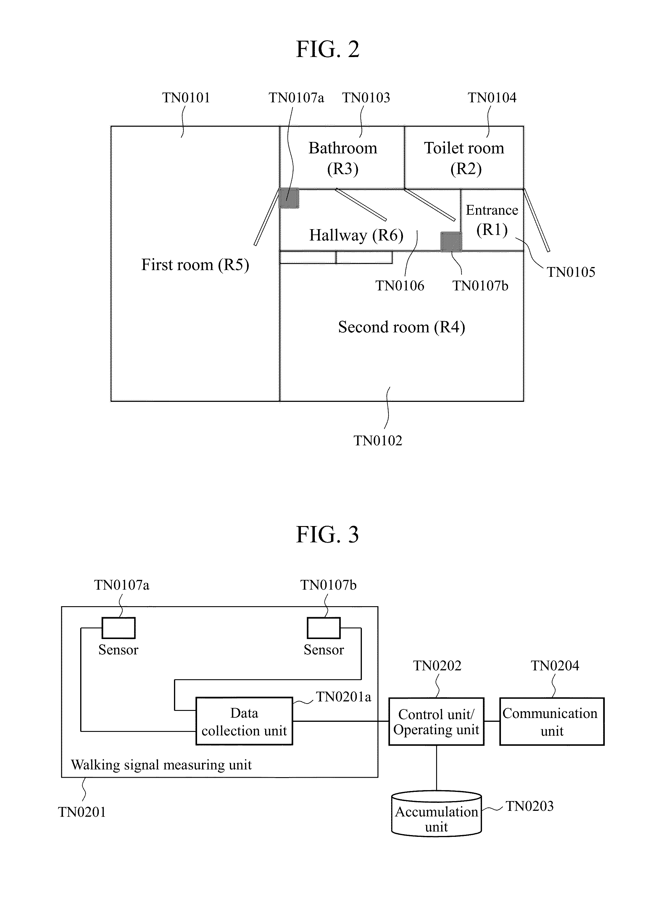
[0050]The facility 1 is provided with a measuring system TN0200 for chronologically measuring the position of the subject in the facility 1. The measuring system TN0200 includes a walking signal measuring unit TN0201 that measures a walking signal using a sensor; a control unit / operating unit TN0202 that controls the walking signal measuring unit TN0201 and executes an arithmetic operating process with respect to the measured signal; an accumulation unit TN0203 that accumulates results of operation by the control unit / operating unit TN0202; and ...
second embodiment
[0150]In the present embodiment, another example of the method of estimating the position of the monitoring subject in the facility 1 will be described. FIG. 20 shows a schematic view illustrating the principle of the position estimation method according to the second embodiment.
[0151]In the position estimation method according to the present embodiment, the difference in sound propagation speed depending on the type of medium is utilized. The walking sound generated when a leg MI10_3 lands on a floor MI10_4 during walking is measured using two microphones including an atmospheric sound microphone MI10_1 and a floor sound microphone MI10_2. The atmospheric sound microphone MI10_1 and the floor sound microphone MI10_2 are installed at mutually proximate positions. The atmospheric sound microphone MI10-1 observes sound transmitted through the air, while the floor sound microphone MI10-2 observes sound transmitted through the floor.
[0152]The propagation speed of sound greatly varies de...
third embodiment
[0156]In the present embodiment, a method of estimating the position of the monitoring subject in the building when the walking sound is so small that it is difficult to observe the walking sound as vibrations will be described.
[0157]When the walking sound cannot be observed even though the monitoring subject is moving, debilitation of the monitoring subject can be suspected. Thus, it is desirable to be able to detect the debilitation using the monitoring system for monitoring health state. However, if the walking sound cannot be observed, the location of the monitoring subject cannot be identified by the above-described method, and it cannot be detected whether the subject is moving. In this case, in order to identify the location of the monitoring subject, not only the walking sound information but also another position detection method may be used.
[0158]For that purpose, one method employs distance sensors that utilize reflection of electromagnetic waves, such as ultrasonic waves...
PUM
 Abstract
Description
Claims
Application Information