
Internet-Based Video Delivery System

a video delivery system and video technology, applied in the field of internet-based video delivery system, can solve the problems of inconvenient expert, inability to analyze time-sensitive events in real time, and cost of tv programs

Active Publication Date: 2015-12-10
VIDEOLINK
View PDF3 Cites 4 Cited by
  • Summary
  • Abstract
  • Description
  • Claims
  • Application Information

AI Technical Summary

Benefits of technology

The present system and method deliver content over the Internet using an overlay network built on the underlying IP network. The system includes error correction capability to allow the destination to reconstitute packets lost during the transmission over the Internet. The system uses a plurality of overlay nodes, which may be geographically distributed, either throughout the country or throughout the world. Overhead, capable of providing error correction capability, is added to the content flow as it enters the overlay network. As the content flow leaves the overlay network, this overhead is removed from the content flow. In the case of transmission errors across the overlay network, the overhead information is used to reconstitute lost packets.

Problems solved by technology

This involves costs for the television program, and an inconvenience for the expert.
In addition, such an arrangement does not allow for real-time analysis of time-sensitive events, such as breaking news, corporate mergers, or political reaction, as the experts need time and sufficient notice to travel to the studio.
The communication infrastructure required to transmit the video feed from the remote studio to the control location may be expensive.
The fiber-based long distance transmission model involves a high installation cost, high monthly recurring cost and modest per-usage cost.
In addition, such equipment may only be able to control one camera at a time.

Method used


Image

  • Internet-Based Video Delivery System
  • Internet-Based Video Delivery System
  • Internet-Based Video Delivery System

Examples


Embodiment Construction

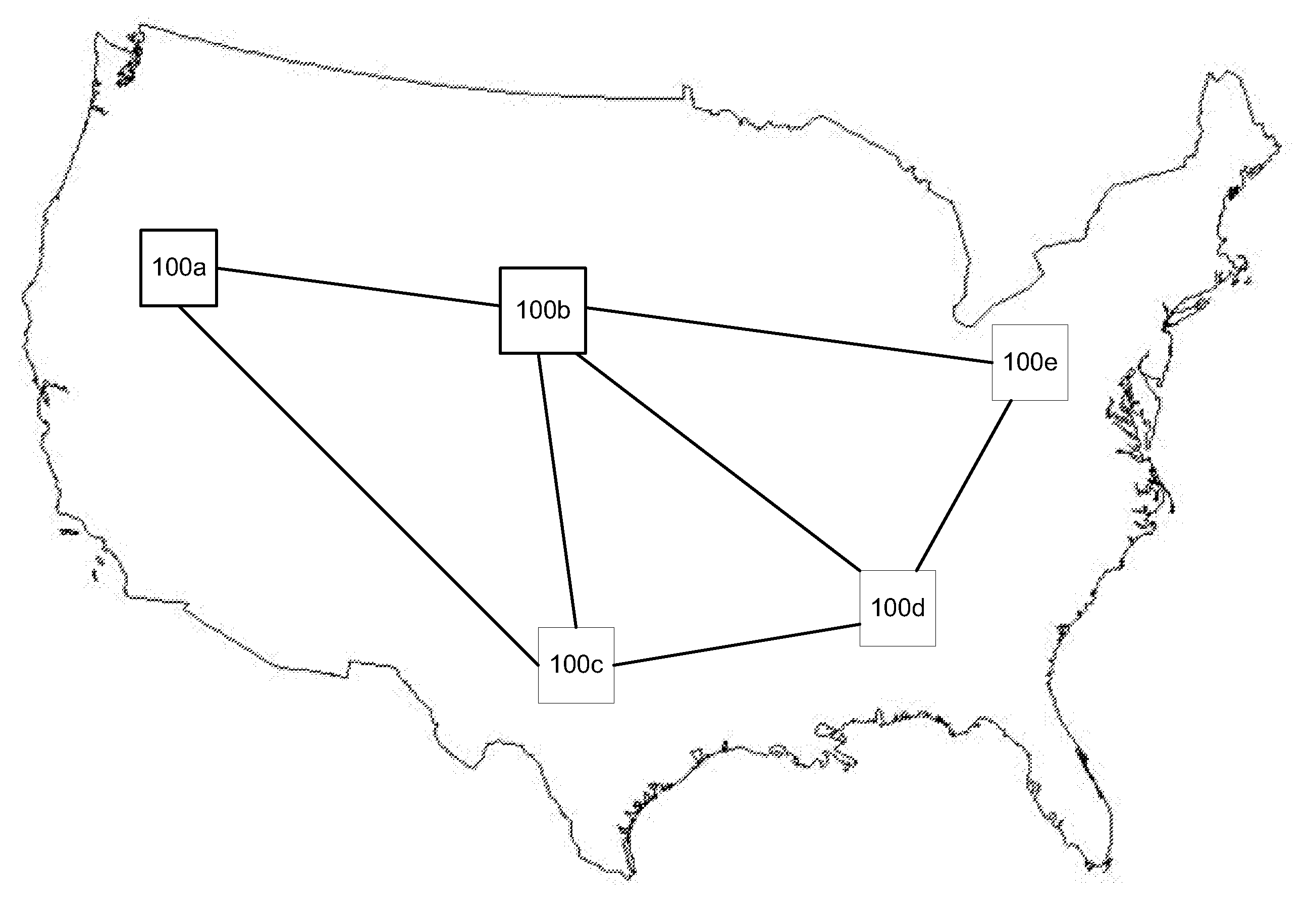
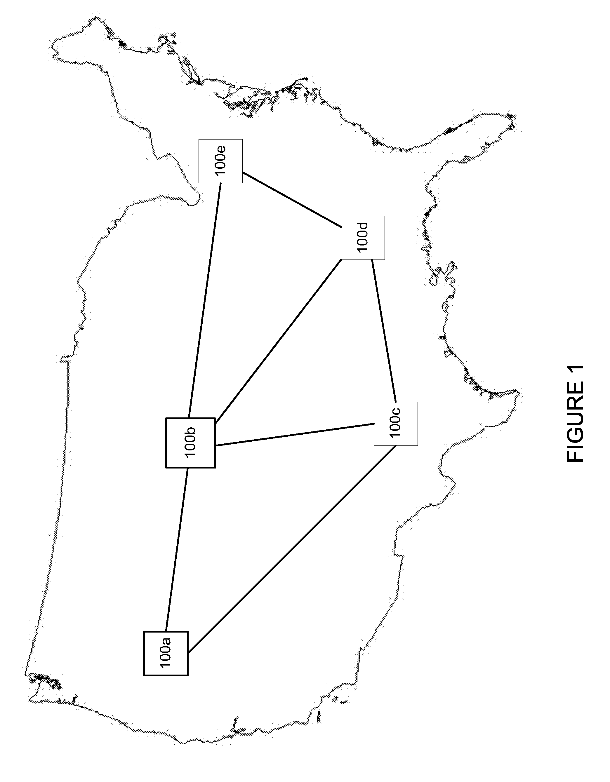
[0014]FIG. 1 shows a representative overlay network 10 in accordance with one embodiment. The overlay network includes a number of nodes 100a-e, which may be geographically dispensed across the transmission region of interest. While FIG. 1 shows the overlay networks located in the United States, the invention is not limited to this embodiment. For example, one or more nodes may be located in other countries. Additionally, there is no upper limit to the number of overlay nodes that may be included in the overlay network.

[0015]The overlay network serves to create reliable or semi-reliable transmissions across the underlying IP network. This overlay network may be a message-oriented overlay network (MOON), although other types of overlay networks may also be used. In one embodiment, the overlay network may be based on the implementation known as SPINES, available from www.spines.org. In other embodiments, the MOON may be based on Resilient Overlay Network (RON), available from the Mass...


PUM


Abstract

A system and method for delivering content over the Internet from a content source to a destination is disclosed which includes the use of an overlay network, built on an underlying IP network. Additionally, error correction capability is added to the overlay network to allow the destination to reconstitute packets lost during the transmission over the Internet. In one embodiment, an overlay network is created using a plurality of overlay nodes, which may be geographically distributed, either throughout the country or throughout the world. Each respective content source or destination is also a part of the overlay network. Overhead, capable of providing error correction capability, is added to the content flow as it enters the overlay network. As the content flow leaves the overlay network, this overhead is removed from the content flow. In the case of transmission errors across the overlay network, the overhead information is used to reconstitute lost or corrupted packets.

Description

[0001]This application is a continuation of U.S. patent application Ser. No. 13 / 796,053 filed Mar. 12, 2013, which claims priority of U.S. Provisional Patent Application Ser. No. 61 / 728,012, filed Nov. 19, 2012, the disclosures of which are incorporated herein by reference in its entirety.BACKGROUND OF THE INVENTION[0002]The flood of news, financial, political and other informational television programs has generated an ever increasing demand to utilize on-air experts, such as investment bankers, lawyers, and politicians. The presence of these experts adds credibility and an in-depth analysis of a given topic that is not otherwise possible.[0003]Traditionally, for this interview to occur, the expert is forced to travel to the television studio of the television show that is interested in interviewing this expert. This involves costs for the television program, and an inconvenience for the expert. For example, the expert would have to travel to the studio, where they are prepared for...

Claims


Application Information

Patent Timeline
Patent Type & Authority Applications(United States)
IPC IPC(8): H04N21/422H04N21/61H04N21/462
CPCH04N21/42204H04N21/6156H04N21/4622H04N21/2187H04N21/2221H04N21/64322H04N21/6473H04N21/64776H04L45/64H04N21/6125H04L65/765H04N23/661
Inventor AKIMCHUK, III, JAMES W.WILLIS, LEIGH
Owner VIDEOLINK
Learn More