
Method of handover in mobile communication system

a mobile communication system and terminal technology, applied in the field of handover methods for terminals in mobile communication systems, can solve the problems of increasing data interruption time during handover, difficult to transmit real-time handover commands from serving base stations to terminals, and difficulty in real-time transmission of signal strength reports from terminals to serving base stations, so as to achieve greater signal strength of first target base stations

Active Publication Date: 2015-12-10
ELECTRONICS & TELECOMM RES INST
View PDF3 Cites 23 Cited by
  • Summary
  • Abstract
  • Description
  • Claims
  • Application Information

AI Technical Summary

Benefits of technology

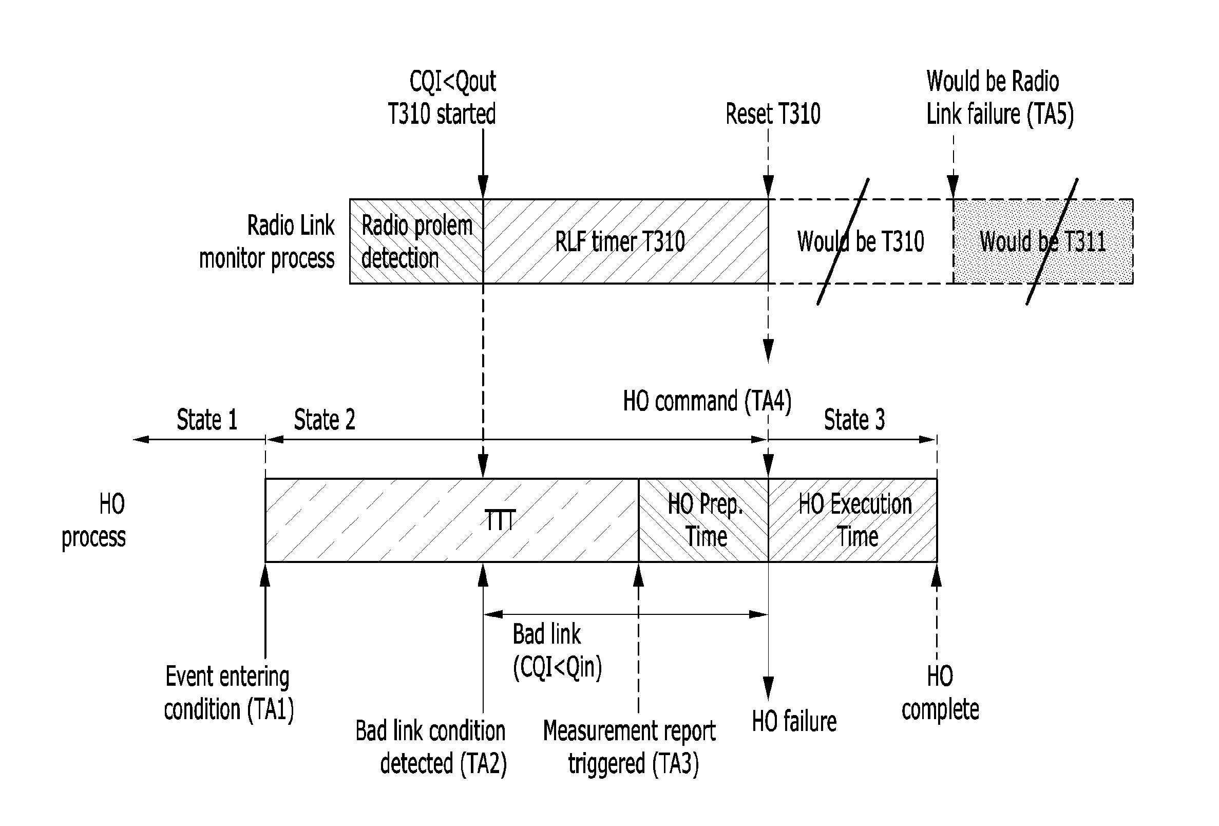
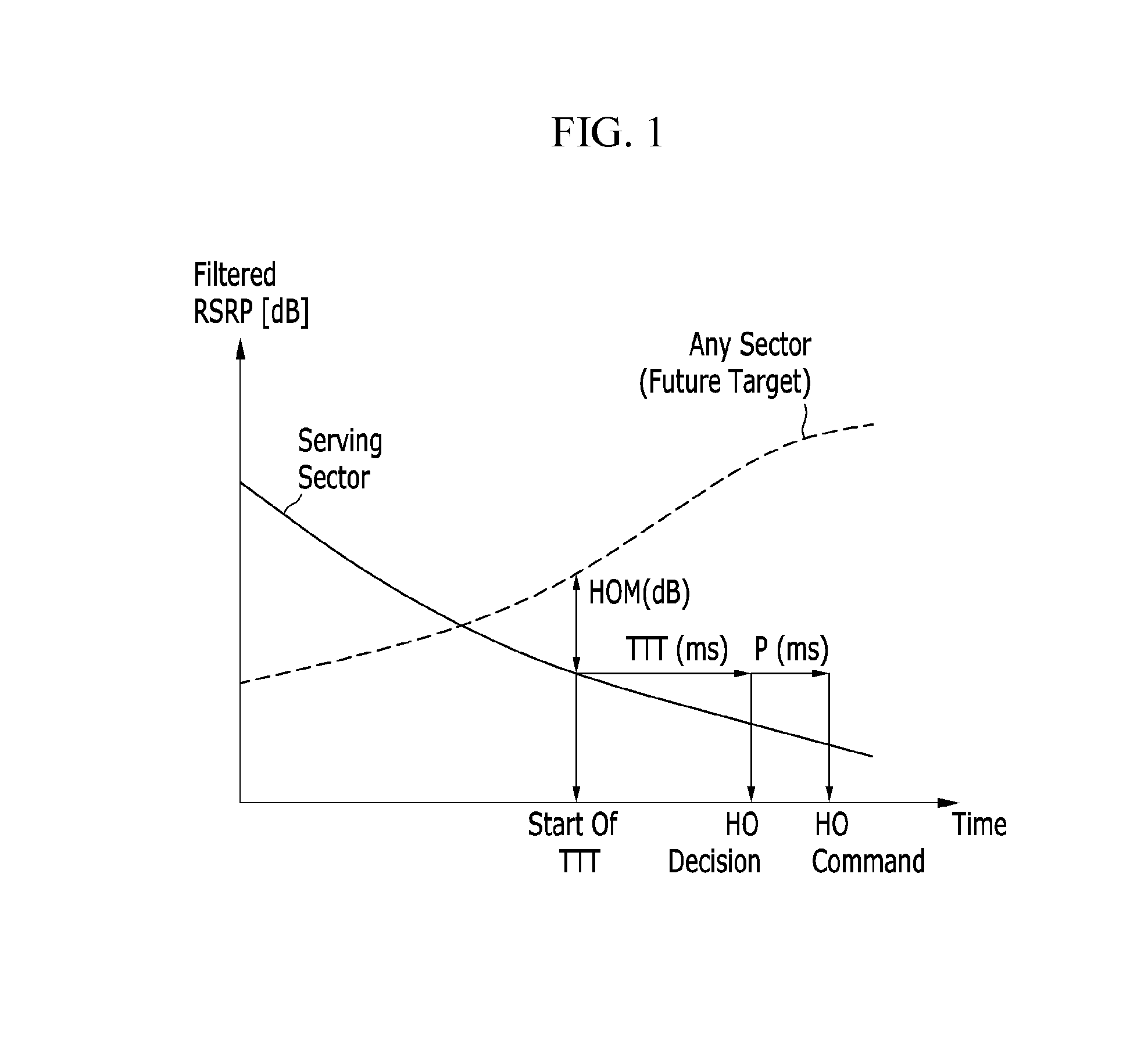
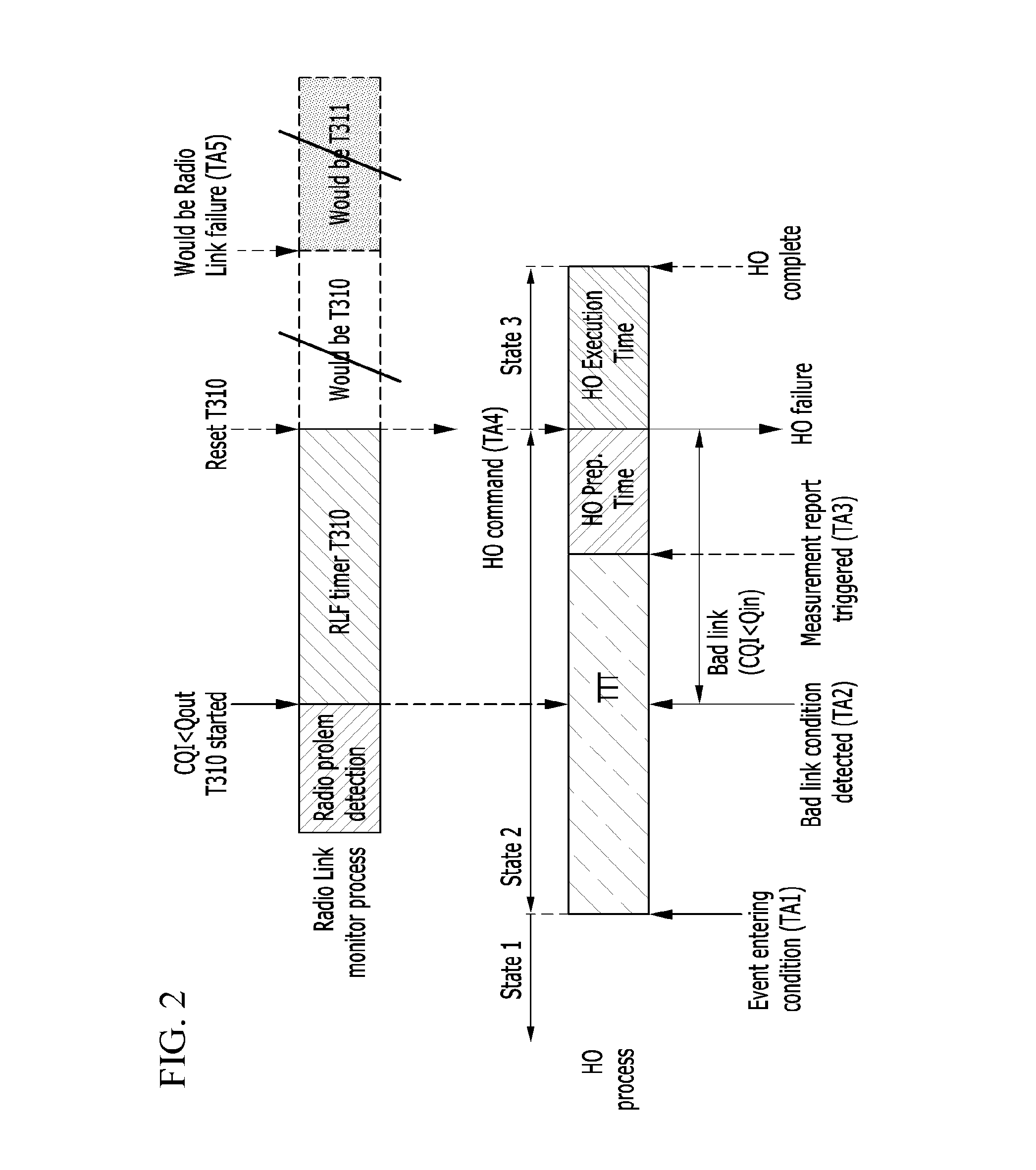
The present invention provides a handover method and a communication method for a terminal in a mobile communication system. The handover method includes a first timer for detecting a RLF (Radio Link Failure), a second timer for triggering a handover without a TTT (Time to Trigger), and a measurement report message transmitting the signal strength of the target base station to the serving base station. The method also includes a handover execution time for the terminal to determine when to execute the handover based on the signal strength of the target base station and the handover command message received from the serving base station. The invention helps prevent RLF and improves the handover performance of the terminal.

Problems solved by technology

However, if a radio link in a handover area (temporal area or spatial area) is in a bad condition, it is difficult to transmit the signal strength report from the terminal to the serving base station in real time, and it is also difficult to transmit the handover command from the serving base station to the terminal in real time.
Due to this, data interruption time during handover increases, and communication quality drops at the time of handover.
Due to this, a radio link failure (RLF) may occur.
Data is interrupted during this operation, causing the communication quality to drop.

Method used


Image

  • Method of handover in mobile communication system
  • Method of handover in mobile communication system
  • Method of handover in mobile communication system

Examples


Embodiment Construction

[0030]In the following detailed description, only certain exemplary embodiments of the present invention have been shown and described, simply by way of illustration. As those skilled in the art would realize, the described embodiments may be modified in various different ways, all without departing from the spirit or scope of the present invention. Accordingly, the drawings and description are to be regarded as illustrative in nature and not restrictive. Like reference numerals designate like elements throughout the specification.

[0031]In the specification, a terminal may indicate a mobile terminal (MT), an advanced mobile station (AMS), a high reliability mobile station (HR-MS), a subscriber station (SS), a portable subscriber station (PSS), an access terminal (AT), and user equipment (UE), and it may include entire or partial functions of the terminal, MT, MS, AMS, HR-MS, SS, PSS, AT, and UE.

[0032]In the specification, a base station (BS) may indicate an advanced base station (AB...


PUM


Abstract

A terminal starts a first timer for detecting an RLF (Radio Link Failure) when signal strength of a serving base station is lower than a reference value. The terminal triggers a handover without a TTT (Time to Trigger) for handover when signal strength of a target base station is greater than the signal strength of the serving base station by a first offset or more while the first timer is running. The terminal transmits a measurement report message regarding the signal strength of the target base station to the serving base station when a handover is triggered.

Description

CROSS-REFERENCE TO RELATED APPLICATION[0001]This application claims priority to and the benefit of Korean Patent Application Nos. 10-2014-0068296 and 10-2015-0009535 filed in the Korean Intellectual Property Office on Jun. 5, 2014 and Jan. 20, 2015, the entire contents of which are incorporated herein by reference.BACKGROUND OF THE INVENTION[0002](a) Field of the Invention[0003]The present invention relates to a handover method for a terminal in a mobile communication system.[0004](b) Description of the Related Art[0005]LTE (Long Term Evolution) mobile communication systems are in commercial use and provide services throughout the world. In LTE, a terminal performs a handover when moving from one base station to another. Specifically, the terminal reports the signal strength of surrounding base stations to a serving base station. The serving base station prepares a target base station to which the terminal will perform a handover, based on the signal strength report from the termina...

Claims


Application Information

Patent Timeline
IPC IPC(8): H04W36/00H04W24/10
CPCH04W36/0055H04W36/24H04W36/08H04W24/10H04W36/0058H04W36/305H04W36/302
Inventor PARK, HYUN SEOCHOI, YONG SEOUK
Owner ELECTRONICS & TELECOMM RES INST
Learn More