Input device, method of manufacturing the same, and electronic information equipment

a manufacturing method and input device technology, applied in the direction of instruments, coatings, computing, etc., can solve the problems of difficult to make such electrodes operate as touch switches, difficult to achieve the effect of reducing the sensitivity of detection with respect to capacitance, and complex structure of electrodes, so as to achieve the effect of enhancing the visibility of an image and suppressing uneven shading

Active Publication Date: 2015-12-24
SHARP KK
View PDF1 Cites 30 Cited by
  • Summary
  • Abstract
  • Description
  • Claims
  • Application Information

AI Technical Summary

Benefits of technology

[0051]According to the present invention as described above, it is possible to realize: an input device, which can make areas of individual divided sections of a conductive line uniform at a row electrode and a column electrode made by patterning a meshed conductive layer by forming the divided sections on conductive lines constituting a meshed conductive layer, and thereby suppress uneven shading due to the patterned meshed conductive layer from appearing on a touch operation surface for a touch operation or a proximity operation formed by the row electrode and the column electrode, resulting in enhancement of the visibility of an image of a display surface recognized through the touch operation surface; a method of manufacturing the same; and electronic information equipment using such an input device.

Problems solved by technology

For this reason, when a large touch panel is manufactured, sensitivity of detection with respect to capacitance decreases with the increase in the resistance value between terminals of a row electrode or a column electrode such that it becomes difficult to make such electrodes operate as a touch switch.
Thus, the structure of the electrodes is complex, and an electrode forming process requires a step of patterning at least two layers of conductive layers and a step of forming an insulation film for insulating the top and bottom conductive layers.
Such a capacitive touch panel 60 using a meshed metallic layer for row and column electrodes has problems, such as uneven shading appearing on a surface of the touch panel due to dislocation in the bonding of the two sensor sheets, or uneven shading appearing due to a difference in line widths between a metallic line of the meshed metallic layer constituting the row electrode, and a metallic line of the meshed metallic layer constituting the column electrode.

Method used


Image

  • Input device, method of manufacturing the same, and electronic information equipment
  • Input device, method of manufacturing the same, and electronic information equipment
  • Input device, method of manufacturing the same, and electronic information equipment

Examples


embodiment 1

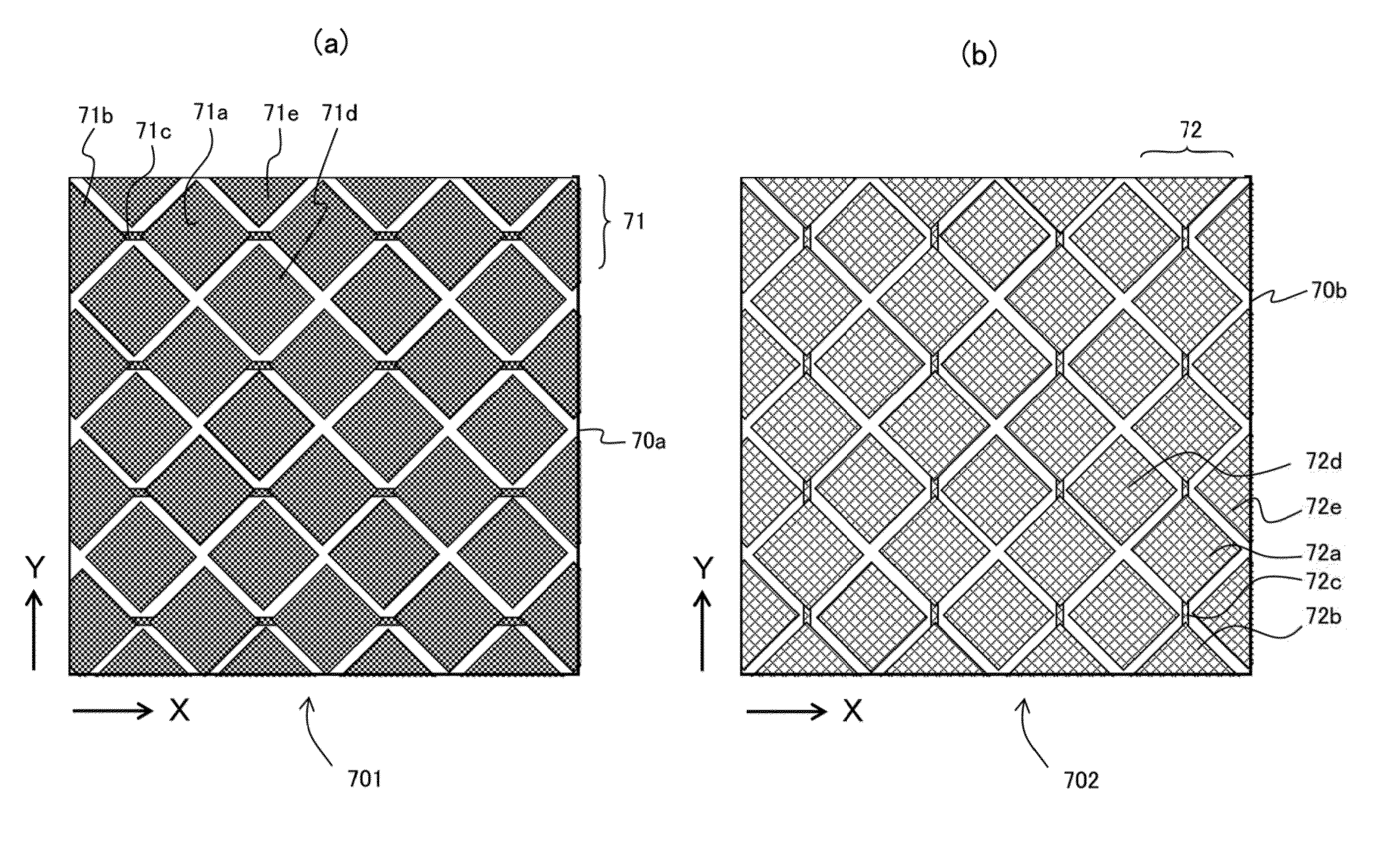
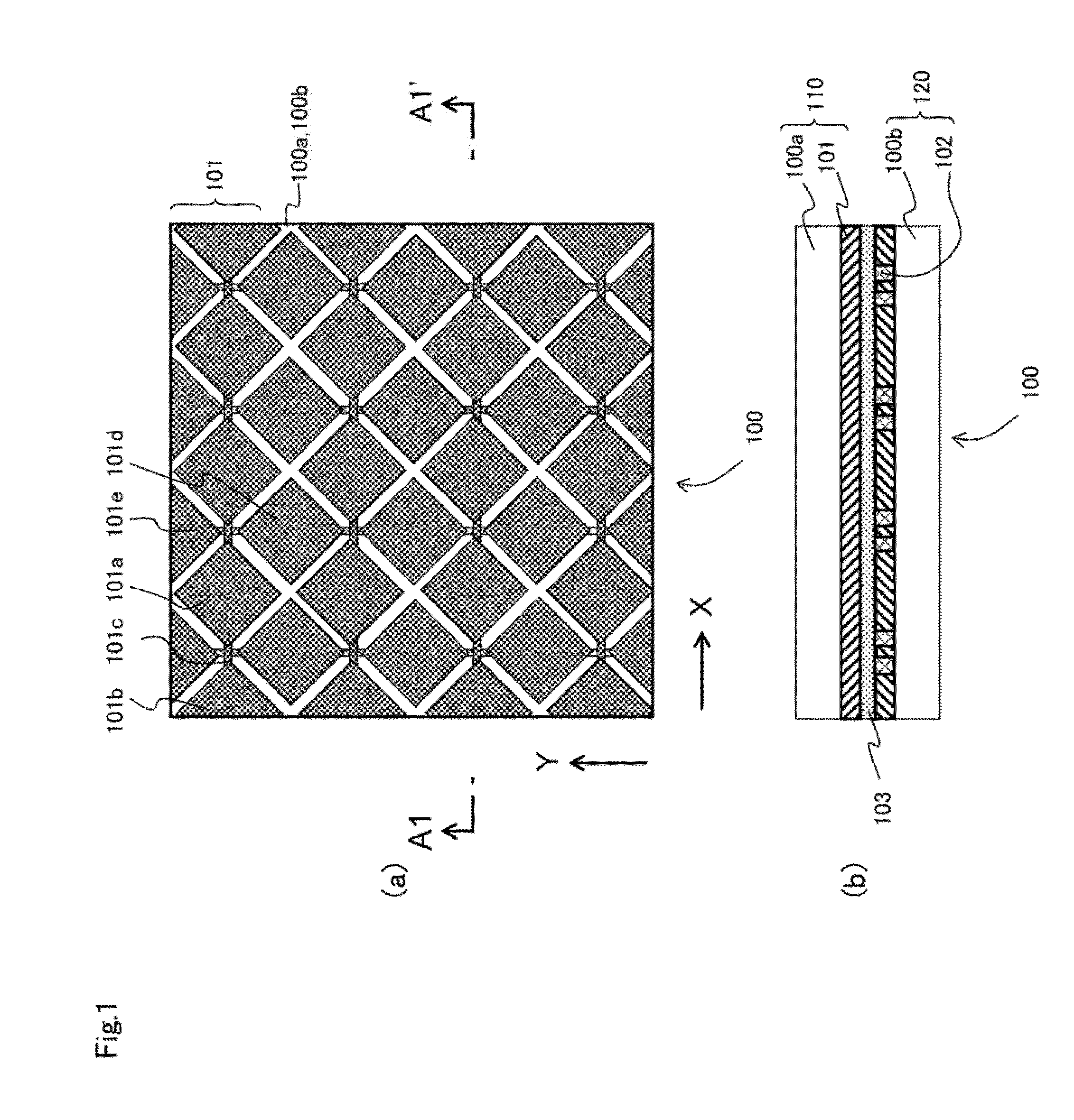
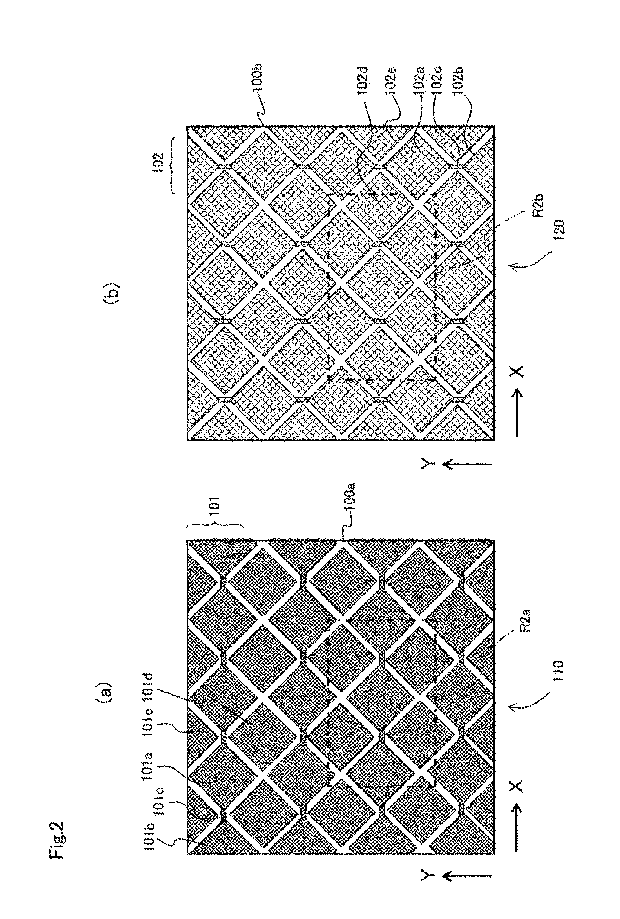
[0083]FIG. 1 and FIG. 2 are diagrams for explaining a capacitive touch panel as an input device according to Embodiment 1 of the present invention. FIG. 1(a) shows an arrangement of electrodes of this touch panel. FIG. 1(b) shows a cross-sectional structure of this touch panel (portion at A1-A1′ line of FIG. 1(a)). FIGS. 2(a) and 2(b) show row electrodes and column electrodes formed on each insulation sheet substrate, respectively.

[0084]This touch panel 100 fundamentally has a configuration similar to that of the conventional touch panel 70 shown in FIGS. 16 and 17. In other words, the touch panel 100 has a first sensor sheet 110 made by patterning a meshed metallic layer (meshed conductive layer) formed on an insulation sheet substrate (insulation substrate) 100a consisting of a transparent insulation material such as PET, such that a row electrode (first meshed electrode) (X sensor) 101 is formed, and a second sensor sheet 120 made by patterning a meshed metallic layer (meshed con...

embodiment 2

[0116]FIG. 8 is a diagram for explaining a capacitive touch panel as an input device according to Embodiment 2 of the present invention. FIG. 8(a) shows a dividing section of a metallic line for an intersecting position of the metallic line of a meshed metallic layer and a contour of a column electrode when forming the column electrode of the touch panel by patterning the meshed metallic layer. FIG. 8(b) shows the enlarged A8 portion of FIG. 8(a).

[0117]In addition to the configuration of the touch panel of Embodiment 1, the touch panel of Embodiment 2 has a structure in which a mesh side section in a metallic line Mw2 having two intersecting positions of the metallic line Mw2 of the meshed metallic layer and an ideal contour Sp2 (division band Db2) of the column electrode is divided at a center position Cpr between two intersecting positions Cp1 and Cp2.

[0118]A mask pattern of such a column electrode can be obtained by setting a square region Rs for dividing the metallic line Mw2 at...

embodiment 3

[0124]FIG. 9 is a diagram for explaining a capacitive touch panel that is an input device according to Embodiment 3 of the present invention. FIG. 9(a) shows a divided part of a metallic line for an intersecting position of the metallic line of a meshed metallic layer and an ideal contour Sp2 of a column electrode when forming the column electrode of this touch panel by patterning the meshed metallic layer. FIG. 9(b) shows an enlarged dividing section Dp of the column electrode corresponding to the A9 portion of FIG. 9(a).

[0125]In addition to the configuration of the touch panel in Embodiment 2, the touch panel of Embodiment 3 has a structure in which at a section where an intersection Mcp of the metallic lines of the meshed metallic layer overlaps with a division band Db2 along the ideal contour Sp2 of the column electrode for the patterning of the column electrode, a metallic line Mw2 is divided at three places that are separated by a certain distance from the intersection Mcp. A ...


PUM


Abstract

An input device having a row electrode and a column electrode made by patterning a meshed metallic layer by forming a dividing section on a metallic line constituting the meshed metallic layer can make areas of individual dividing sections of the metallic lines uniform, whereby uneven shading due to the patterned, meshed conductive layer is suppressed from appearing on a touch operation surface.
In the input device having the row electrode and the column electrode made by patterning the meshed metallic layer by forming the dividing section on the metallic line constituting the meshed metallic layer, at an intersecting section where metallic lines Mw2 constituting a meshed conductive layer Lp2 intersects an ideal contour Sp2 of a meshed column electrode, the direction for dividing the metallic lines at the intersecting section is set to the direction matching the direction of width of the metallic lines such that the area of the dividing section traversing the metallic line is minimal.

Description

TECHNICAL FIELD[0001]The present invention relates to an input device, a method of manufacturing the same, and electronic information equipment, and specifically relates to an input device for detecting an input operation based on a change in capacitance between adjacent electrodes among a plurality of electrodes arranged on an input operation surface, a method of manufacturing the same, and electronic information equipment using such an input device.BACKGROUND ART[0002]In recent years, electronic information equipment such as a computer or a mobile phone, which enables an input operation utilizing a display of a display device, has been developed. A touch panel (also called a touch sensor) used in combination with a display device is installed as an input device in such electronic information equipment.[0003]There are various forms of touch panels, such as the resistive film type, surface acoustic wave type, and infrared type touch panels. However, touch panels of capacitive type (...

Claims


Application Information

Patent Timeline
Patent Type & Authority Applications(United States)
IPC IPC(8): G06F3/044G06F1/16G06F3/041
CPCG06F3/044G06F3/0412G06F2203/04103G06F2203/04112G06F1/16G06F3/0445G06F3/0446G06F2203/04111
Inventor HAYASHI, SHOGOKIDA, KAZUTOSHIYASHIRO, YUHJIYOSHIMURA, KAZUYA
Owner SHARP KK
Why Eureka
Try Eureka