Relief device for oil circuit of engine

a technology of oil circuit and relief device, which is applied in the direction of lubrication pressure control, machines/engines, pressure lubrication, etc., can solve the problems of large energy loss, difficult detail control of valves, and obstruct the improvement of fuel consumption at low temperature, so as to achieve accurate control and reduce oil pressure. , the effect of high accuracy

Inactive Publication Date: 2015-12-31
YAMADA SEISAKUSHO KK
View PDF7 Cites 3 Cited by
  • Summary
  • Abstract
  • Description
  • Claims
  • Application Information

AI Technical Summary

Benefits of technology

[0011]Therefore, the object of the present invention (the problem to be solved by the present invention) is to provide an inexpensive and highly reliable relief device for an oil circuit of an engine, whereby substantially the same oil pressure characteristics can be achieved irrespective of the oil temperature, and in particular, decline in fuel consumption at low temperature can be suppressed, by means of a very simple composition.
[0019]In the configuration of the present invention, since the temperature-sensitive relief valve and the oil-pressure relief valve are connected in parallel, then the control variations of the respective relief valves are not added together, and hence more accurate control is possible. Furthermore, since the temperature-sensitive relief valve has a function of relieving oil by opening and closing steplessly, by detecting the oil temperature, then the temperature-sensitive relief valve is a valve that can be opened and closed steplessly, rather than a so-called on / off type of valve as in the prior art. For example, if the temperature-sensitive relief valve is opened a little, then a small amount of oil only is relieved, and therefore, the oil pressure is reduced only a little, and hence the oil pressure can be adjusted steplessly by adjusting the amount of opening / closing of the temperature-sensitive relief valve. Furthermore, by adopting a configuration wherein an oil filter is provided in the upstream flow passage and the temperature-sensitive relief valve is positioned to the upstream side of the oil filter, the temperature-sensitive relief valve can control the relieving of oil with sufficiently high accuracy, without being affected by differences in the pressure loss in the oil filter due to differences in the oil temperature.

Problems solved by technology

By means of the operation described above, since the oil pressure is higher when the oil temperature is lower, then there is large energy loss and this obstructs improvement in fuel consumption at low temperature.
Furthermore, since the second control valve (7) is a valve which controls the oil pressure, rather than the flow volume, then it is a so-called on / off valve which transmits virtually all of the oil pressure when communicating to any extent, and therefore detailed control of the valve is difficult.

Method used


Image

  • Relief device for oil circuit of engine
  • Relief device for oil circuit of engine
  • Relief device for oil circuit of engine

Examples


first embodiment

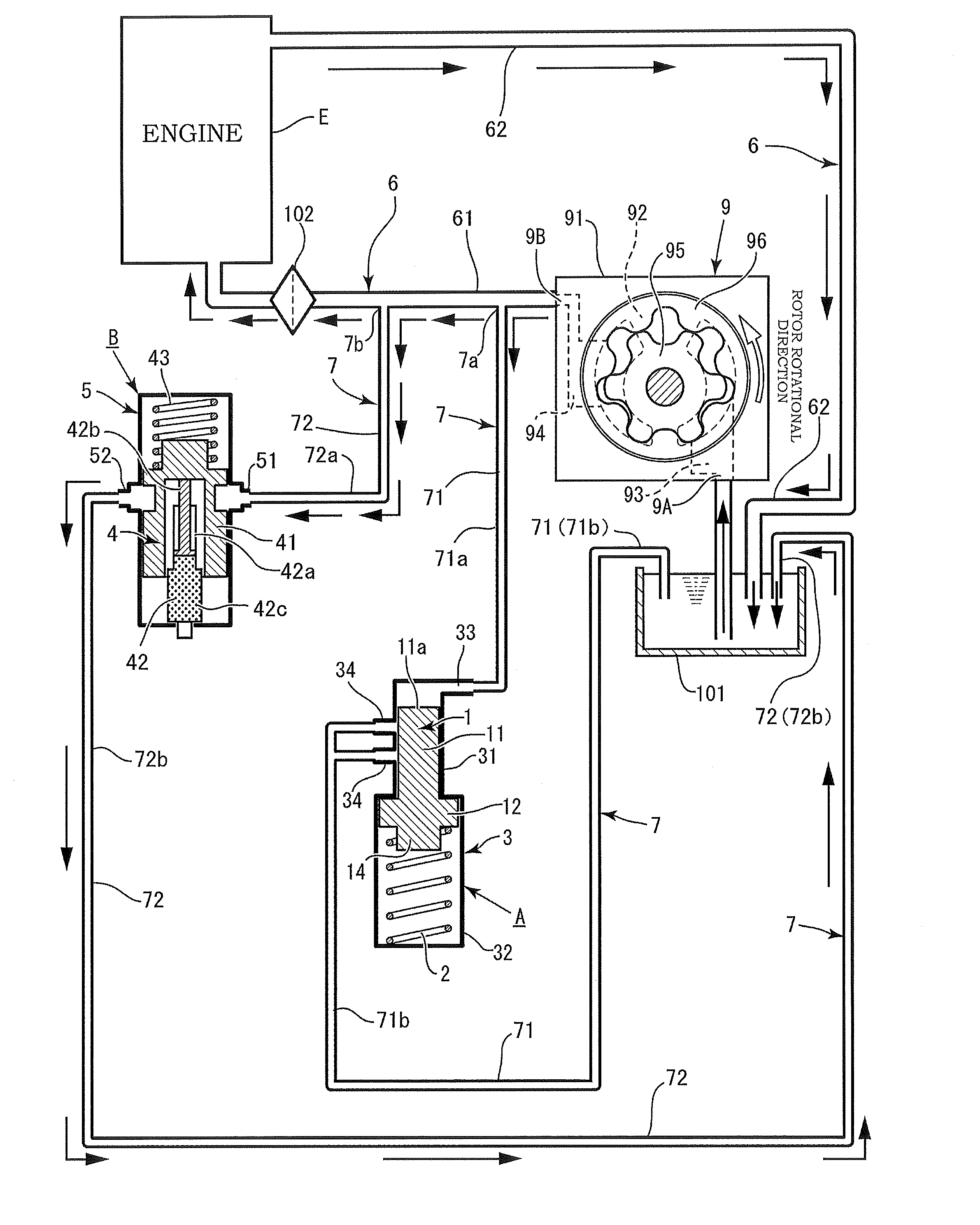
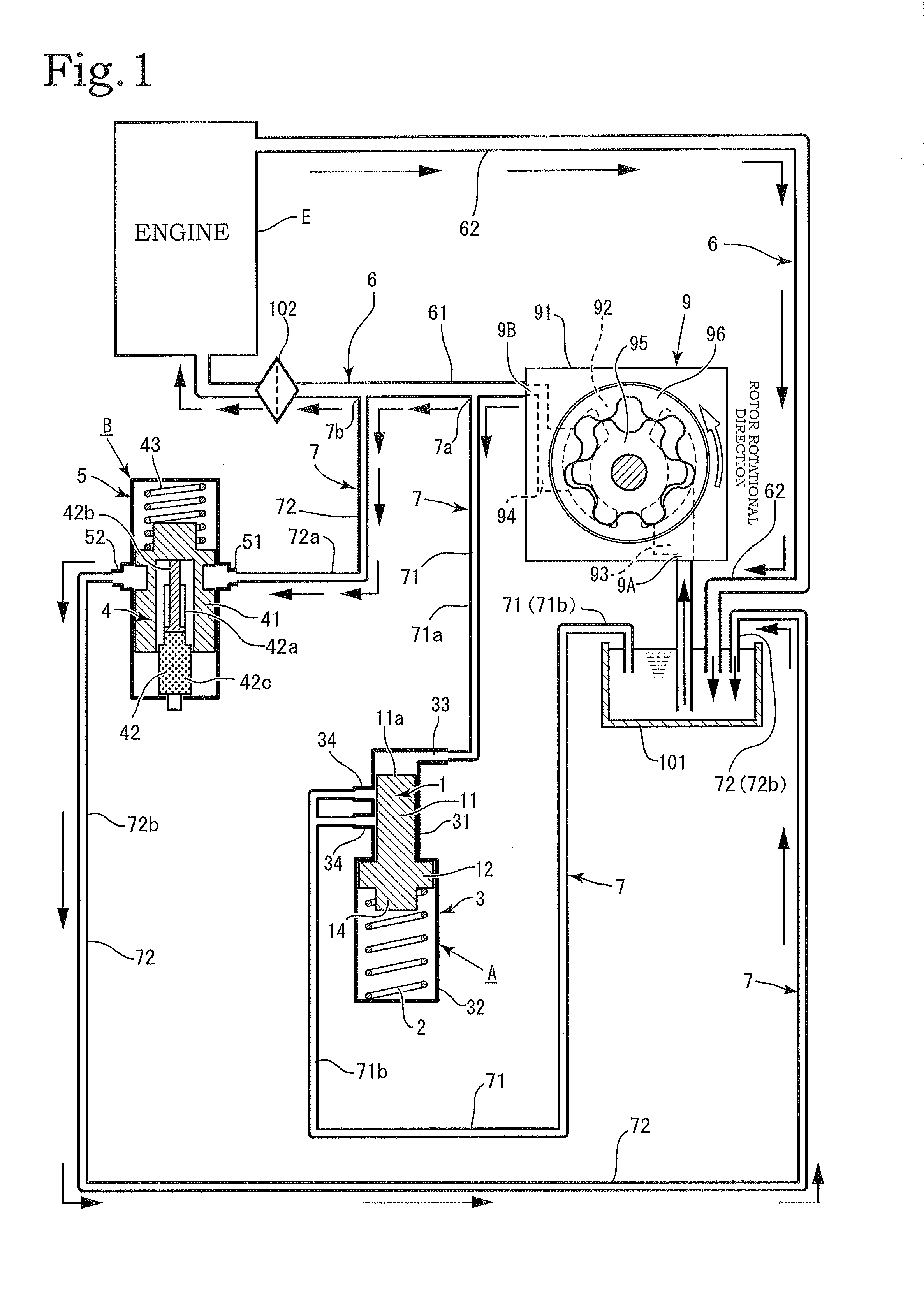
[0054]There are two embodiments for the configuration of the relief flow passage 7, and in the first embodiment, the relief flow passage 7 is divided into a first relief branch flow passage 71 which branches from the upstream flow passage 61 via a first branch section 7a at a position near the oil pump 9, and a second relief branch flow passage 72 which branches via a second branch section 7b at a position near the engine E (see FIG. 1).

[0055]Hence, the first relief branch flow passage 71 and the second relief branch flow passage 72 server as parallel flow passages, and the oil-pressure relief valve A is provided in the first relief branch flow passage 71 and the temperature-sensitive relief valve B is provided in the second relief branch flow passage 72, and by adopting a configuration of this kind, the oil-pressure relief valve A and the temperature-sensitive relief valve B are arranged in parallel.

[0056]The flow passage on the upstream side of the position where the oil-pressure ...

second embodiment

[0059]Moreover, in the relief flow passage 7, one upstream shared flow passage 73 which is connected to the intake section 9A of the oil pump 9 via an intermediate position in the upstream flow passage 61 of the oil circulation circuit 6 is provided, an upstream two-leg branch section′7c is provided at the end of the upstream shared flow passage 73, and the first relief branch flow passage 71 and the second relief branch flow passage 72 are provided in a parallel arrangement bifurcated from the upstream two-leg branch section 7c (see FIG. 8).

[0060]The oil-pressure relief valve A is provided on the side of one of the first relief branch flow passage 71 and the second relief branch flow passage 72, and the temperature-sensitive relief valve B is provided on the other thereof. A downstream two-leg branch merging section 7d is provided in the downstream end portion of the first relief branch flow passage 71 and the second relief branch flow passage 72, and a downstream shared flow passa...

third embodiment

[0086]In the third embodiment, when the oil temperature is medium, the amount of oil relieved by the temperature-sensitive relief valve becomes greater near a low temperature, and becomes smaller near a high temperature. A medium temperature is a temperature range between a low oil temperature and a high oil temperature. Accordingly, in the medium temperature range, there is a large temperature difference between the side near a low temperature and the side near a high temperature. Therefore, a large differential in the viscosity of the oil also occurs within the medium temperature range.

[0087]Consequently, when the oil temperature is medium, the viscosity of the oil is greater and the oil pressure increases, the lower the oil temperature, and the viscosity is smaller and the oil pressure decreases, the higher the oil temperature. Therefore, when the oil temperature is low within the medium temperature range, the temperature-sensitive relief valve implements control so as to increas...


PUM


Abstract

A relief device including: an oil pump; an upstream flow passage provided from a discharge section side of the oil pump to an engine; an oil-pressure relief valve relieving oil by a valve body moving due to oil pressure; and a temperature-sensitive relief valve B relieving oil by detecting an oil temperature and opening and closing steplessly. The oil-pressure relief valve and the temperature-sensitive relief valve are disposed in parallel in the upstream flow passage. A portion of the pump housing of the oil pump is formed in an integrated fashion with a casing of an oil circulation mechanism. An oil filter 102 is provided in the upstream flow passage 61, and the temperature-sensitive relief valve B is positioned on the upstream side of the oil filter.

Description

BACKGROUND OF THE INVENTION[0001]1. Field of the Invention[0002]The present invention relates to a relief device for an oil circuit of an engine, which is provided with an oil-pressure relief valve and a temperature-sensitive relief valve, whereby oil can be relieved (expelled) at a desired oil pressure, regardless of the oil temperature, and which has a simplified configuration.[0003]2. Description of the Related Art[0004]Conventionally, there is a variety of pumps for supplying oil for lubricating and cooling an engine, which are provided with a relief valve that relieves oil when the discharge pressure-exceeds a prescribed value. Moreover, there is also a relief device for an oil circuit of an engine, wherein it is determined whether or not to relieve oil in accordance with change in the temperature of the oil, as well as pressure change.[0005]The third embodiment of Japanese Patent Application Publication No. 2006-214286 is a concrete example of a device of this type. The third ...

Claims


Application Information

Patent Timeline
Patent Type & Authority Applications(United States)
IPC IPC(8): F01M1/10F01M1/02
CPCF01M1/16
Inventor MIYAJIMA, JUNICHIWATANABE, TAKATOSHIKATO, YUYA
Owner YAMADA SEISAKUSHO KK
Why Eureka
Try Eureka