Inlet guide vane mechanism

Active Publication Date: 2015-12-31
CARRIER CORP
View PDF5 Cites 1 Cited by
  • Summary
  • Abstract
  • Description
  • Claims
  • Application Information

AI Technical Summary

Benefits of technology

This patent describes an invention of an inlet guide vane assembly for a compressor in a chiller refrigeration system. The invention includes multiple vane subassemblies that can rotate to control the amount of air flow into the compressor. Each vane subassembly is equipped with a separate drive mechanism for independent rotation. The position of the vane subassemblies is determined by a control system and power is provided to the drive mechanisms to independently move each vane subassembly to the desired position. The technical effects of this invention include improved performance and efficiency of the chiller refrigeration system.

Problems solved by technology

The complex mechanical system for adjusting the position of the inlet guide vanes is labor intensive to manufacture and prone to assembly errors.
In addition, because of the complex connection between an actuator and the vanes, the inlet guide vane assembly is slow to respond to an adjustment thereof.

Method used


Image

  • Inlet guide vane mechanism
  • Inlet guide vane mechanism
  • Inlet guide vane mechanism

Examples


Embodiment Construction

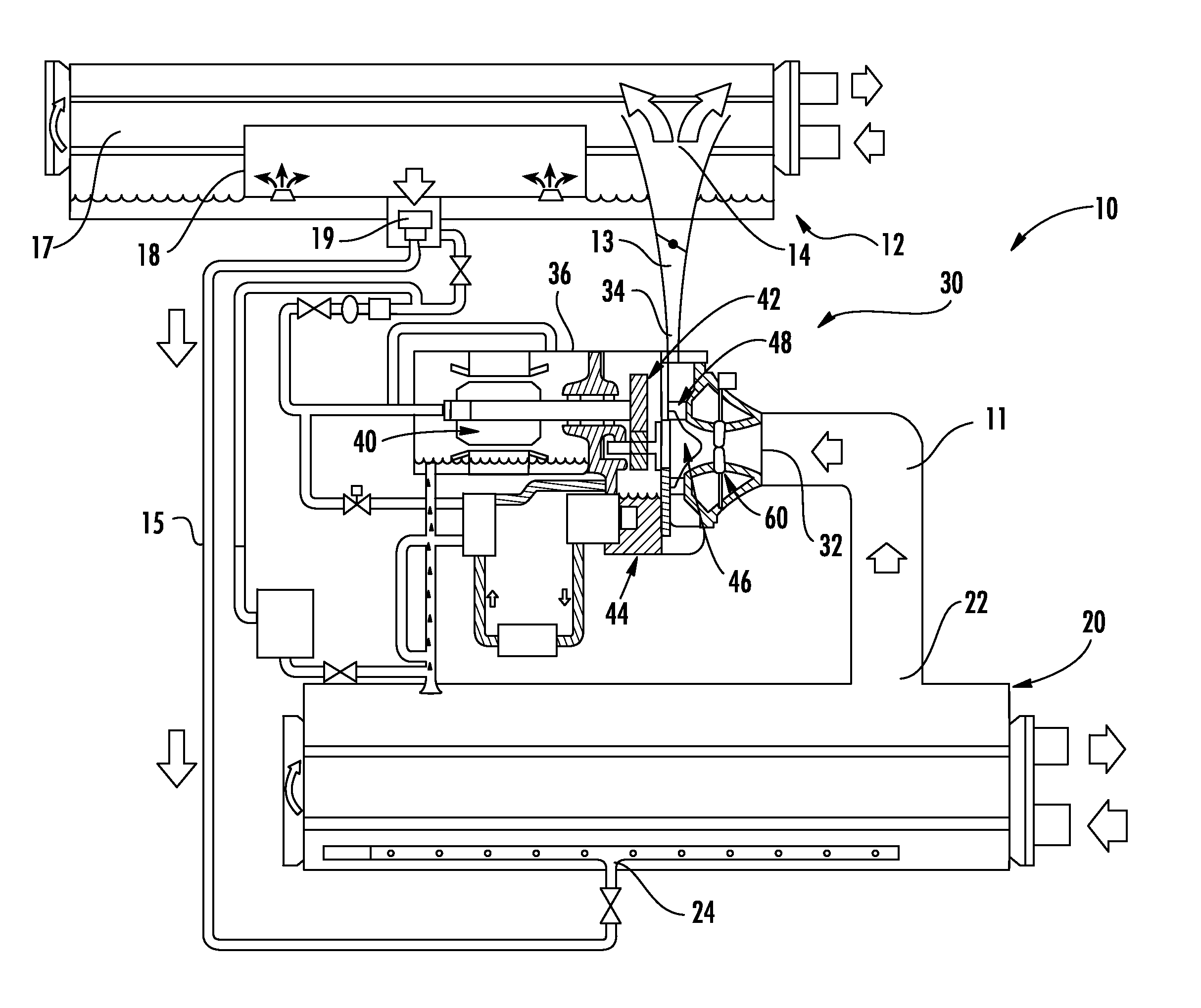
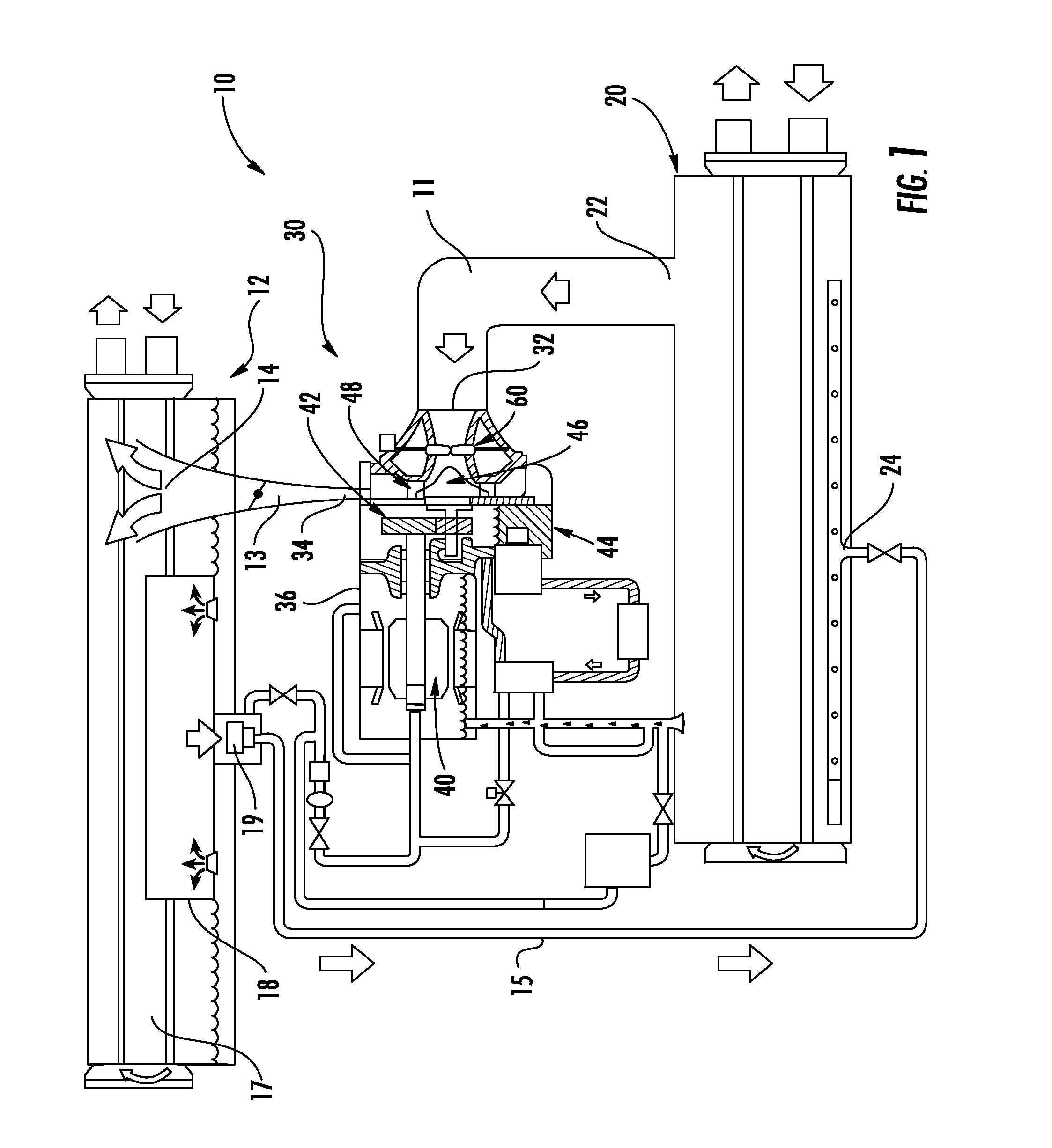
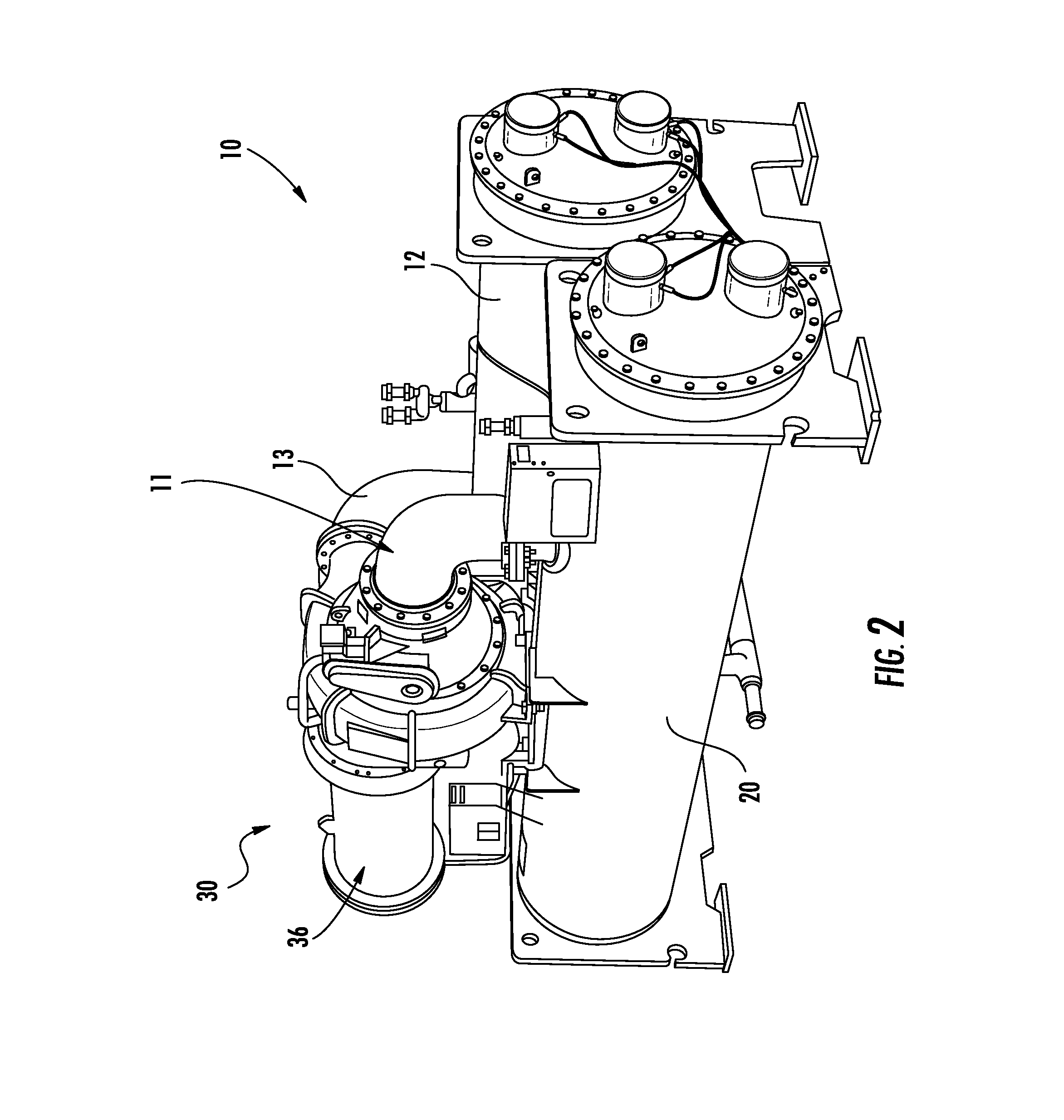
[0018]Referring now to FIGS. 1 and 2, the illustrated exemplary chiller refrigeration system 10 includes a compressor assembly 30, a condenser 12, and a cooler or evaporator 20 fluidly coupled to form a circuit. A first conduit 11 extends from adjacent the outlet 22 of the cooler 20 to the inlet 32 of the compressor assembly 30. The outlet 34 of the compressor assembly 30 is coupled by a conduit 13 to an inlet 14 of the condenser 12. In one embodiment, the condenser 12 includes a first chamber 17, and a second chamber 18 accessible only from the interior of the first chamber 17. A float valve 19 within the second chamber 18 is connected to an inlet 24 of the cooler 20 by another conduit 15. Depending on the size of the chiller system 10, the compressor assembly 30 may include a rotary, screw, or reciprocating compressor for small systems, or a screw compressor or centrifugal compressor for larger systems. A typical compressor assembly 30 includes a housing 36 having a motor 40 at on...


PUM


Abstract

An inlet guide vane assembly (60) is provided including a plurality of vane subassemblies (62) configured to rotate relative to a blade ring housing (64) to control a volume of air flowing there through. The inlet guide vane assembly (60) also includes a plurality of drive mechanisms (80). Each drive mechanism (80) is operably coupled to one of the plurality of vane subassemblies (62). The vane subassemblies (62) may be rotated independently.

Description

CROSS-REFERENCE TO RELATED APPLICATIONS[0001]This application claims the benefit of U.S. provisional patent application Ser. No. 61 / 766,755 filed Feb. 20, 2013, the entire contents of which are incorporated herein by reference.BACKGROUND OF THE INVENTION[0002]The invention relates generally to chiller refrigeration systems and, more particularly, to a method of individually controlling inlet guide vanes at an inlet of a compressor of the chiller refrigeration system.[0003]In many conventional chillers, the compressor, such as a centrifugal compressor for example, is driven by a driving means, such as an electric motor for example, either directly or through a transmission. Optimum performance of the compressor is strongly influenced by the rotating speed of the compressor. The volume of refrigerant flowing through the compressor must be adjusted for changes in the load demanded by the air conditioning requirements of the space being cooled. Control of the flow is typically accomplis...

Claims


Application Information

Patent Timeline
IPC IPC(8): F04D29/44F04D17/10
CPCF04D17/10F04D29/442F04D29/444F04D27/0246F05D2250/51F25B1/053F25B49/022F25B31/026F04D29/462
Inventor SISHTLA, VISHNU M.
Owner CARRIER CORP
Why Eureka
Try Eureka