Method for Processing Multi-Component Video and Images

a multi-component video and image technology, applied in the field of coding pictures and videos, can solve the problems of reducing the coding gains obtained from the cross-component prediction process, and achieve the effect of reducing the coding gains and improving the compression efficiency of the coding system

Inactive Publication Date: 2015-12-31
MITSUBISHI ELECTRIC RES LAB INC
View PDF3 Cites 16 Cited by
  • Summary
  • Abstract
  • Description
  • Claims
  • Application Information

AI Technical Summary

Benefits of technology

[0017]The cross-component prediction sub-process was developed independently from the intra boundary filtering sub-process. When coding camera-captured sequences, both of these processes improve the compression efficiency of the coding system. When coding screen content video, however, the intra boundary filtering process can decrease the coding gains obtained from the cross-component prediction process. Also, the cross-component prediction process uses a boundary-filtered luma residual block to sub-optimally predict a non-boundary-filtered chroma residual block.
[0018]There is a need, therefore, to modify either or both of the cross-component prediction and intra boundary filtering processes so that the inefficiencies introduced by both or either of these processes can be eliminated.

Problems solved by technology

When coding screen content video, however, the intra boundary filtering process can decrease the coding gains obtained from the cross-component prediction process.

Method used


Image

  • Method for Processing Multi-Component Video and Images
  • Method for Processing Multi-Component Video and Images
  • Method for Processing Multi-Component Video and Images

Examples


embodiment 1

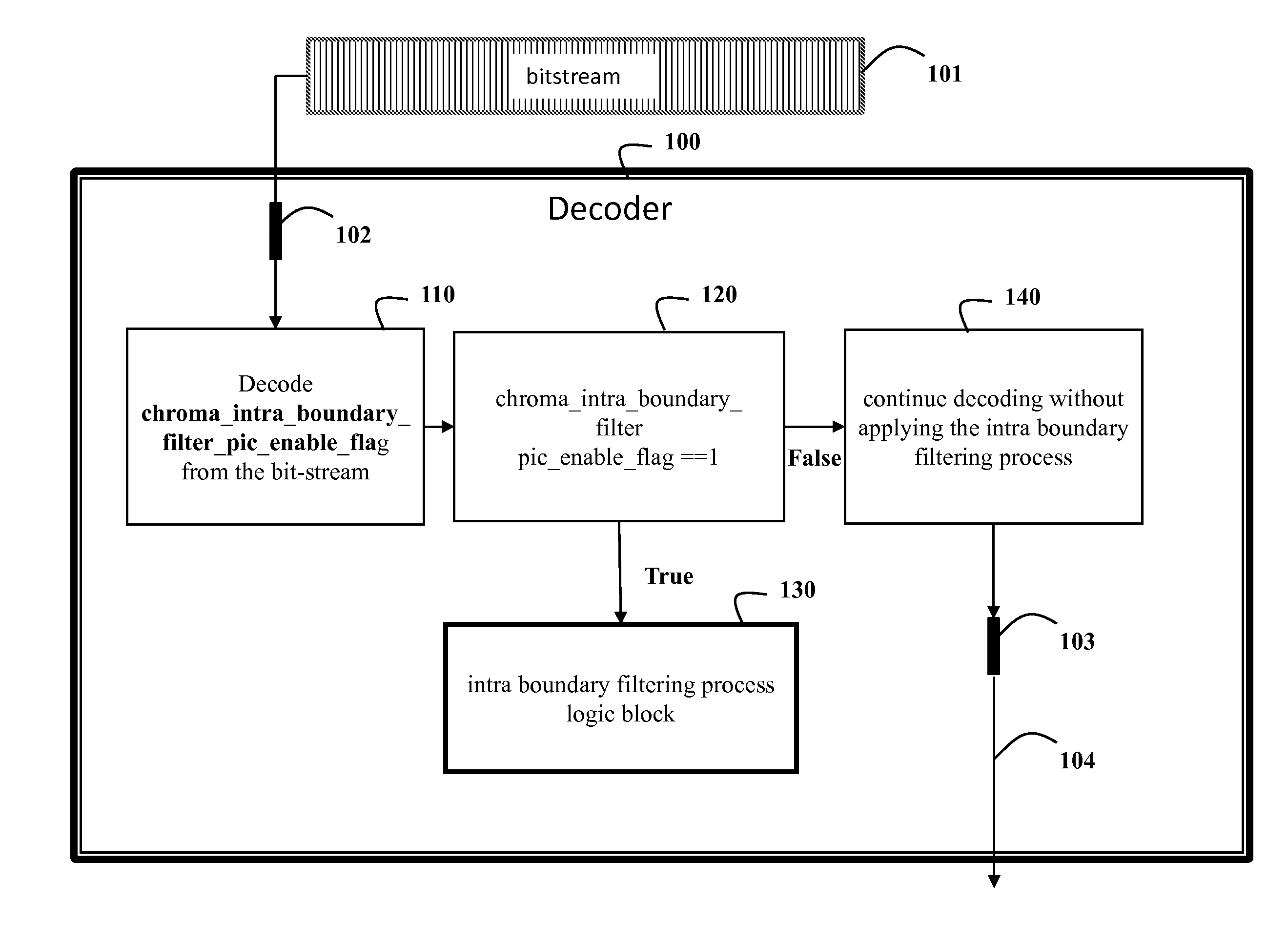
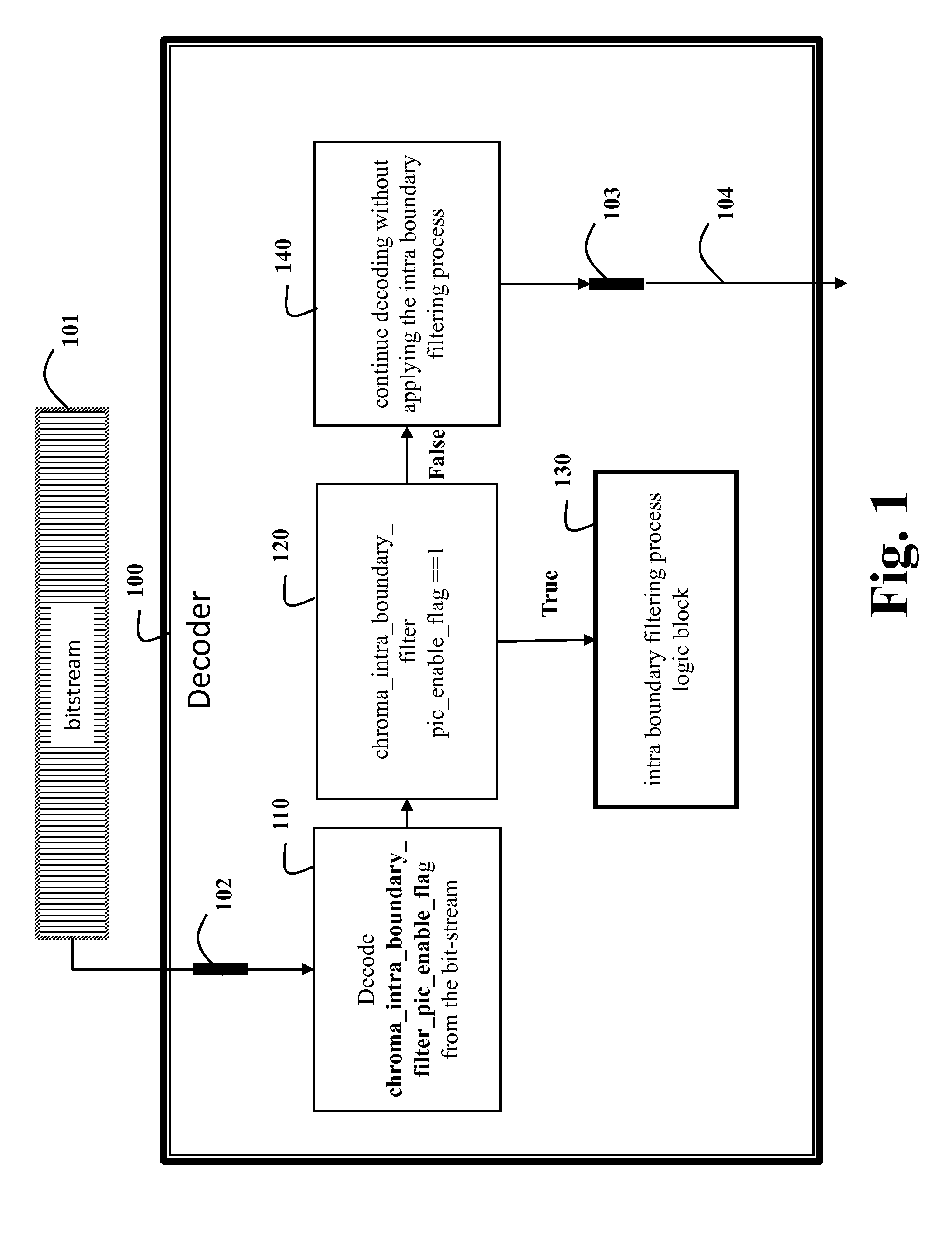
[0024]In this embodiment, a high-level flag is used to indicate the presence of a low-level flag, and the low-level flag indicates whether intra boundary filtering is applied to a component in a picture in a bitstream.

[0025]Table 1 shows definitions of the flags used by embodiments of the invention.

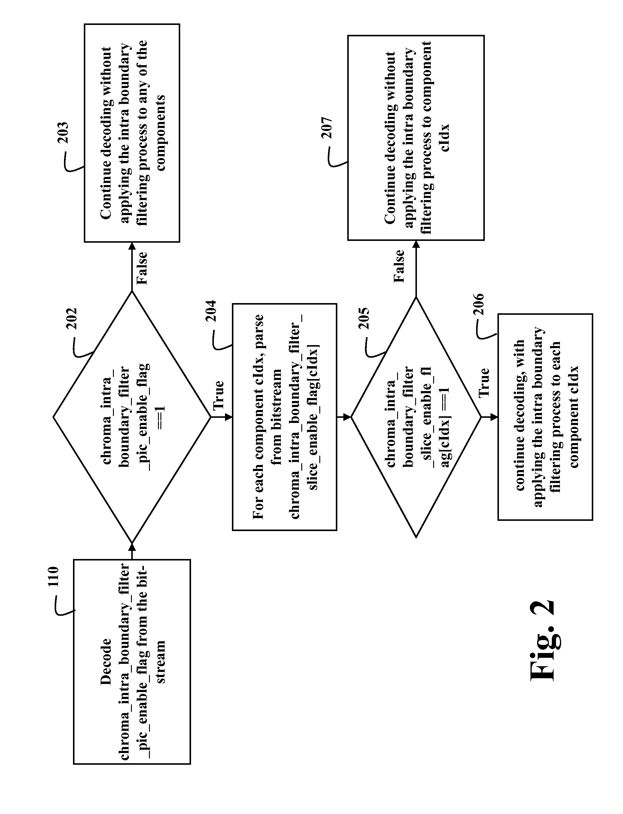
TABLE 1Descriptorseq_parameter_set_rbsp( ) {...cross_component_prediction_enabled_flagu(1)chroma_qp_adjustment_enabled_flagu(1)chroma_intra_boundary_filter_pic_enable_flagu(1)slice_segment_header( ) ( ) {...if( chroma_qp_adjustment_enabled_flag )slice_chroma_qp_adjustment_enabled_flagu(1)If(chroma_intra_boundary_filter_pic_enable_flag)chroma_intra_boundary_filter_slice_enable_flagu(1)...

[0026]Of particular interest are the following flags:

[0027]chroma_intra_boundary_filter_pic_enable_flag==1 specifies the chroma_intra_boundary_filter_slice_enable_flag is present in a slice segment header syntax, and chroma_intra_boundary_filter_pic_enable_flag==0 specifies the chroma_intra_boundary_filter...

embodiment 2

[0035]This embodiment modifies embodiment 1 by using the low-level flag to also enable or disable the application of an offset process to a component. The process for when to apply the offset process is shown in FIG. 3.

[0036]If intra boundary filtering is enabled for the first component, then a chroma_intra_boundary_filter_pic_enable_flag flag is parsed 310 from the bitstream. The value of this flag is checked 320, and if it is false, then intra boundary filtering is not applied to subsequent (chroma) components, so decoding continues 330 by applying the offset process to the subsequent components during cross-component prediction.

[0037]If chroma_intra_boundary_filter_pic_enable_flag is true, then a chroma_intra_boundary_filter_slice_enable_flag flag is parsed 340 from the bitstream.

[0038]The value of this flag is checked 350, and if chroma_intra_boundary_filter_slice_enable_flag is false, then decoding 330 continues by applying the offset process to the subsequent components during...

embodiment 3

[0043]This embodiment is a modification of Embodiment 1, in that the high-level flag and the low-level flag can be used to enable or disable the boundary filtering process for the first component, e.g., luminance, as well as the remaining components, e.g. chrominance. Examples of implementations of this process are to modify the related syntax from the earlier embodiment to remove the dependence on the component index cIdx, so that if ChromalntraBoundaryFilterEnable is equal to 1, then the intra boundary filtering is applied to the component. This modification has the effect of making chroma_intra_boundary_filter_pic_enable_flag and chroma_intra_boundary_filter_slice_enable_flag enable intra boundary filtering for all components.


PUM


Abstract

A method decodes a picture in a form of a bitstream, wherein the picture includes components, by first receiving the bitstream in a decoder. The decoder includes an intra boundary filtering process. A flag is decoded from the bitstream. Then, the intra boundary filtering process is applied, according to the flag.

Description

RELATED APPLICATIONS[0001]This Non-Provisional Application claims priority to U.S. Provisional Application Ser. No. 62 / 018,284, “Method for Processing Multi-Component Video and Images,” filed by Cohen et al. on Jun. 27, 2014.FIELD OF THE INVENTION[0002]The invention relates generally to coding pictures and videos, and more particularly to methods and decoders for predicting and filtering components in pictures in bitstreams and transforming prediction residuals the pictures and videos in the context of encoding and decoding.BACKGROUND OF THE INVENTION[0003]In “HEVC Range Extensions text specification: Draft 6,” a video or sequence of pictures is compressed. Parts of this process include computing prediction residuals between a block of pixels currently being coded and previously-coded pixels. The difference between the input block of pixels and the prediction block is a prediction residual block. The prediction residual block is typically transformed, quantized, and signaled in a bi...

Claims


Application Information

Patent Timeline
Patent Type & Authority Applications(United States)
IPC IPC(8): H04N19/593H04N19/61H04N19/55H04N19/174H04N19/117
CPCH04N19/117H04N19/174H04N19/55H04N19/593H04N19/86H04N19/105H04N19/70H04N19/136H04N19/186H04N19/61
Inventor COHEN, ROBERTZHANG, XINGYUVETRO, ANTHONY
Owner MITSUBISHI ELECTRIC RES LAB INC
Why Eureka
Try Eureka