AI technical title is built by Patsnap AI team. It summarizes the technical point description of the patent document.
a control system and aero-thermo model technology, applied in control systems, testing/monitoring, instruments, etc., can solve the problems of inability to direct measurement of system parameters controlled, lack of accuracy, and limited non-linearity of control systems,
Active Publication Date: 2016-01-07
RTX CORP
View PDF7 Cites 23 Cited by
Summary
Abstract
Description
Claims
Application Information
AI Technical Summary
This helps you quickly interpret patents by identifying the three key elements:
Problems solved by technology
Method used
Benefits of technology
Benefits of technology
The patent describes a control system for a gas turbine engine that uses a model to control the engine's operation. The system includes a model processor that generates the model based on information about the engine and its components. The model processor uses a series of cycle synthesis modules, each designed to model a specific component of the engine. The system also includes an estimate state module that determines the current state of the model based on a prior state model and the current state of the engine. The system can also include a control law that directs the engine's actuator based on the model. The control system can be used to control the engine's position, rate, and dynamic compensation. The patent also describes the use of configurable utilities in the model, as well as the use of one or more mathematical abstractions to model the physical properties of the engine's components. Overall, the control system helps to improve the engine's performance and efficiency.
Problems solved by technology
Further, because direct measurements of system parameters controlled may not be possible (due to undeveloped technology, prohibitive cost, unreliable equipment, etc.), the control system may require real time estimation of system parameters.
These control systems, by their nature, were limited to relatively simple non-linear systems.
Another approach used in the past relies on semi-empirical relationships that tie important system parameters to control sensors; the drawback of such a system is that it may lack accuracy and is expensive due to the additional hardware required for implementation.
Other attempts have been made to deploy stationary simulations in a retail environment; however, by their nature, these models are large, use iterative solvers, have high maintenance cost and lack robustness critical in a real time environment.
Method used
Image
Click on the blue label to locate the original text in one second.
Reading with bidirectional positioning of images and text.
Examples
Embodiment Construction
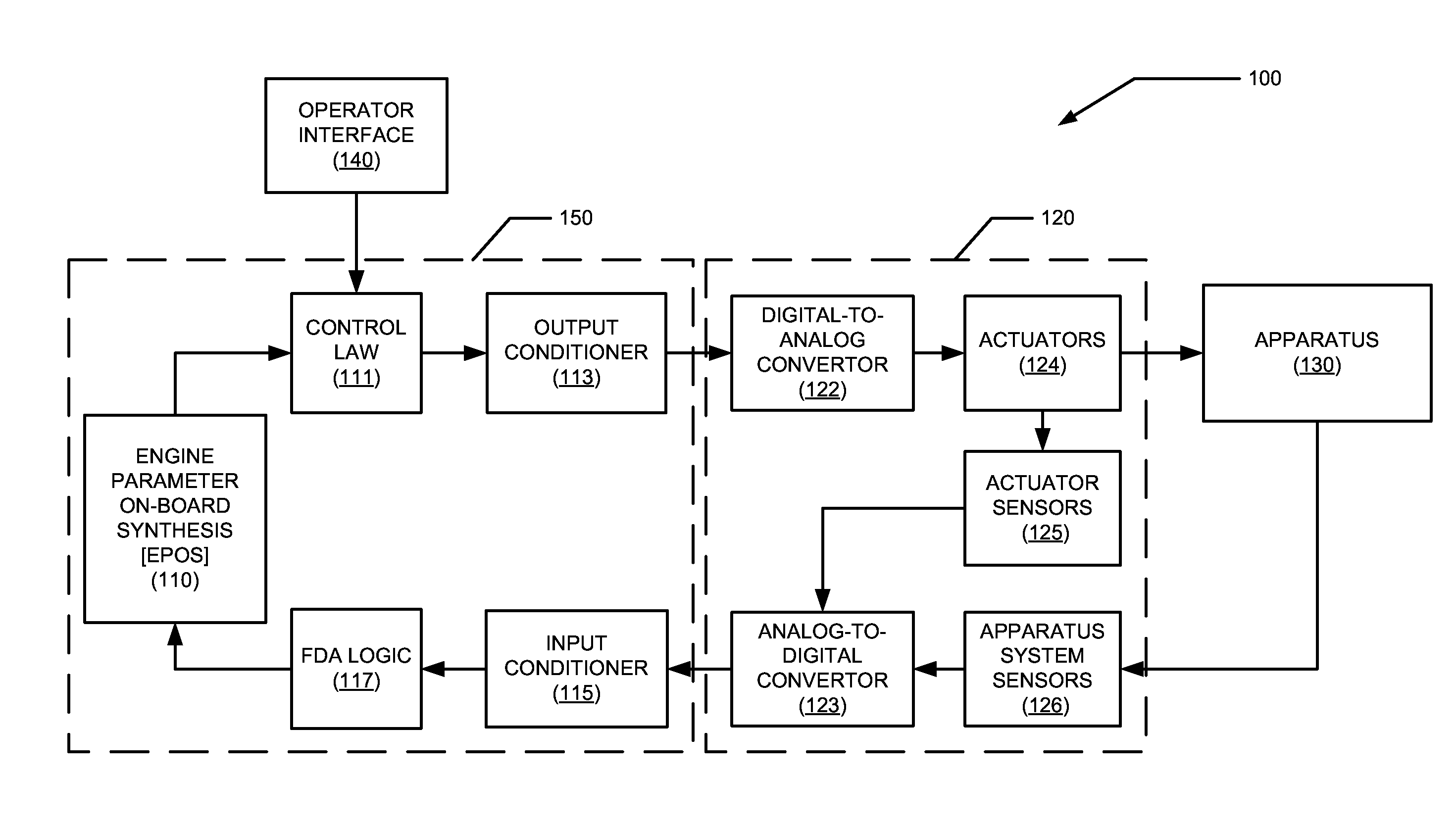
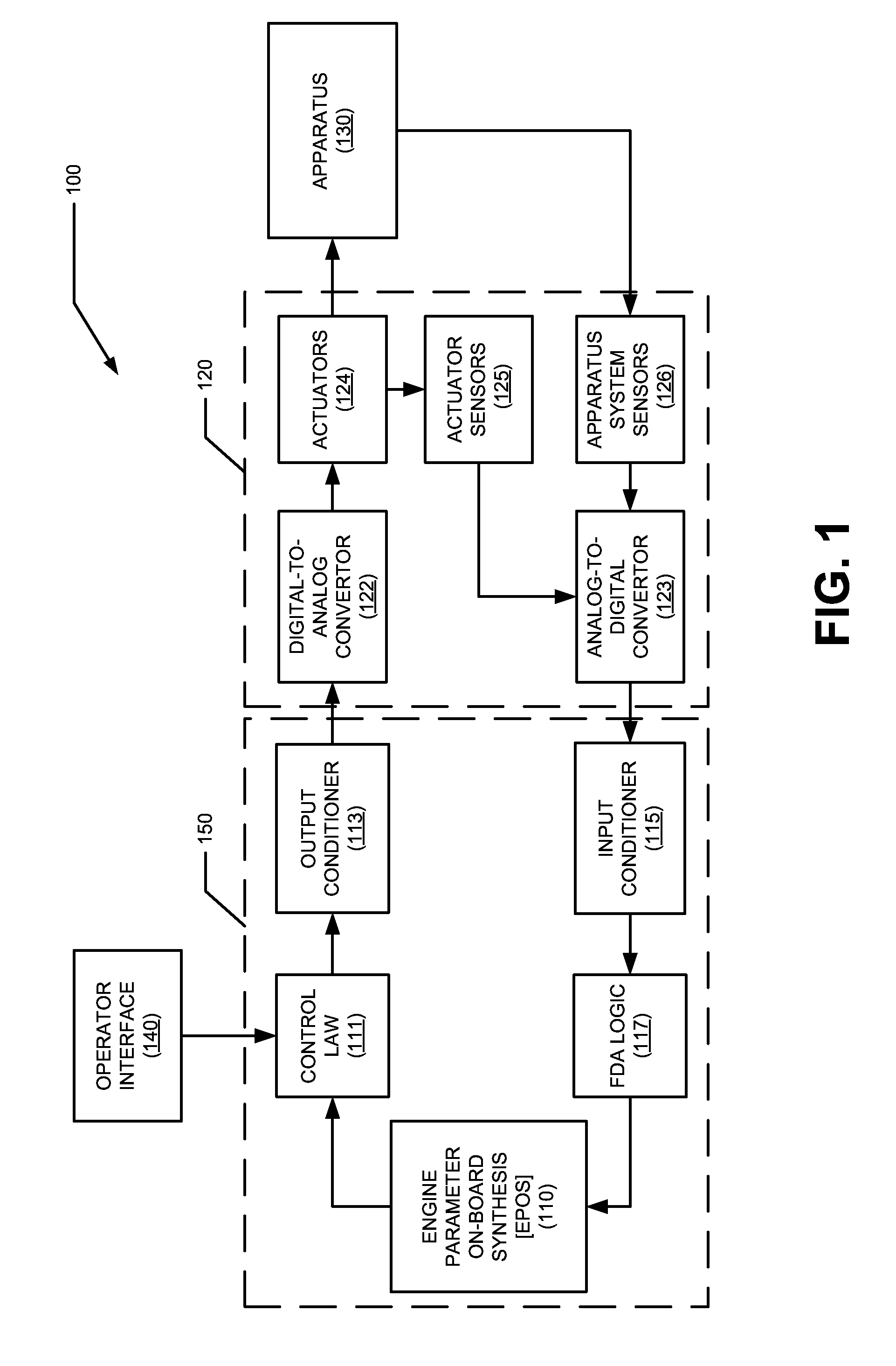
[0039]Referring to the drawings and with specific reference to FIG. 1, a control system for a fluid-based engineering system in accordance with the present disclosure is generally referred to by reference numeral 100. Control demands may be generated by an operator interface 140 and may be received by the engine parameter on board synthesis (EPOS) 110. For example, the operator interface 140 may be a real-time interface such as a cockpit navigation system and / or an operator workstation. Additionally or alternatively, the operator interface 140 may include another, more generalized process control interface, which is suitable for logging control commands to software control components 150, including, for example, a guidance, navigation, and control computer or autopilot system(s). Further, control demands may be generated by an internal memory or any other internal programming operatively associated with software control elements 150.
[0040]The control elements 150 may include EPOS 11...
PUM
Abstract
Systems and methods for controlling a fluid based engineering system are disclosed. The systems and methods may include a model processor for generating a model output, the model processor including a set state module for setting dynamic states of the model processor, the dynamic states input to an open loop model based on the model operating mode, wherein the open loop model generates a current state model as a function of the dynamic states and the model input, wherein a constraint on the current state model is based a series of cycle synthesis modules, each member of the series of cycle synthesis modules modeling a component of a cycle of the control system and including a series of utilities, the utilities are based on mathematical abstractions of physical properties associated with the component. The model processor may further include an estimate state module for determining an estimated state of the model based on a prior state model output and the current state model of the open loop model.
Description
[0001]This application is a US National Stage under 35 USC §371 of International Patent Application No. PCT / US14 / 27636 filed on Mar. 14, 2014 based on U.S. Provisional Patent Application Ser. No. 61 / 800,440 filed on Mar. 15, 2013.TECHNICAL FIELD OF THE DISCLOSURE[0002]The present disclosure relates to the design and control of engineering systems, and more particularly, to design and control of fluid-based engineering systems.BACKGROUND OF THE DISCLOSURE[0003]Fluid-based engineering systems are widely used and may include gas turbine engines for aviation and power generation, HVAC&R (heating, ventilation, air-conditioning and refrigeration), fuel cells, and other, more generalized fluid processing systems for hydrocarbon extraction, materials processing, and manufacture. These systems may contain any or all of the following components: turbo-machinery, fuel cell stacks, electric motors, pipes, ducts, valves, mixers, nozzles, heat exchangers, gears, chemical apparatuses and other dev...
Claims
Application Information
Patent Timeline
Application Date:The date an application was filed.
Publication Date:The date a patent or application was officially published.
First Publication Date:The earliest publication date of a patent with the same application number.
Issue Date:Publication date of the patent grant document.
PCT Entry Date:The Entry date of PCT National Phase.
Estimated Expiry Date:The statutory expiry date of a patent right according to the Patent Law, and it is the longest term of protection that the patent right can achieve without the termination of the patent right due to other reasons(Term extension factor has been taken into account ).
Invalid Date:Actual expiry date is based on effective date or publication date of legal transaction data of invalid patent.
Patent Type & AuthorityApplications(United States)

