Portable device, charging system, and power source circuit substrate

a technology of power source circuit and portability, applied in the direction of electric vehicles, transportation and packaging, electric power, etc., to achieve the effect of preventing the operation of driving components

Active Publication Date: 2016-01-07
HIMPP
View PDF12 Cites 56 Cited by
  • Summary
  • Abstract
  • Description
  • Claims
  • Application Information

AI Technical Summary

Benefits of technology

[0040]The present invention provides a portable device, a charging system, and a power source circuit substrate, in which the handling in activating a function of stopping the operation of a driving component during the charging is improved as the prohibition of the operation of the driving component during the charging and the allowance of the operation of the driving component upon the end of the charging are automatically switched in accordance with whether there is power supply from the outside.

Problems solved by technology

This is not disadvantageous when, for example, the driving component is a mobile phone, because the mobile phone is required to perform its function even during the charging.

Method used


Image

  • Portable device, charging system, and power source circuit substrate
  • Portable device, charging system, and power source circuit substrate
  • Portable device, charging system, and power source circuit substrate

Examples


embodiment 1

Structure of Power Source Circuit Substrate 1

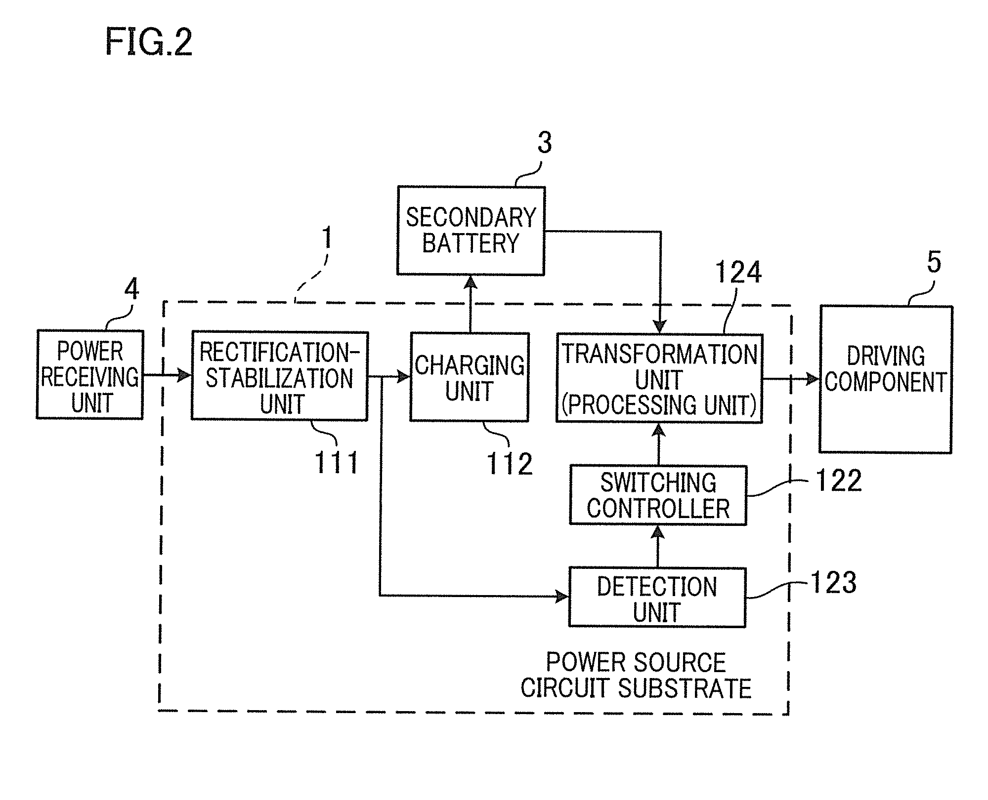
[0059]To begin with, a power source circuit substrate 1 of Embodiment 1 will be described. As shown in FIG. 2, the power source circuit substrate 1 includes a rectification-stabilization unit 111 configured to output DC power by rectifying AC power supplied from the outside via a power receiving unit 4 from which the AC power is output, a charging unit 112 configured to supply, at a charging voltage, the DC power output from the rectification-stabilization unit 111 to a secondary battery 3 which is chargeable and dischargeable, a transformation unit (processing unit) 124 configured to perform signal processing, a detection unit 123 configured to detect the input of the power to the charging unit 112, and a switching controller 122 configured to switch the transformation unit (processing unit) 124 from an operation state to a stopped state only when the detection unit 123 detects the input of the power to the charging unit 112. The power s...

embodiment 2

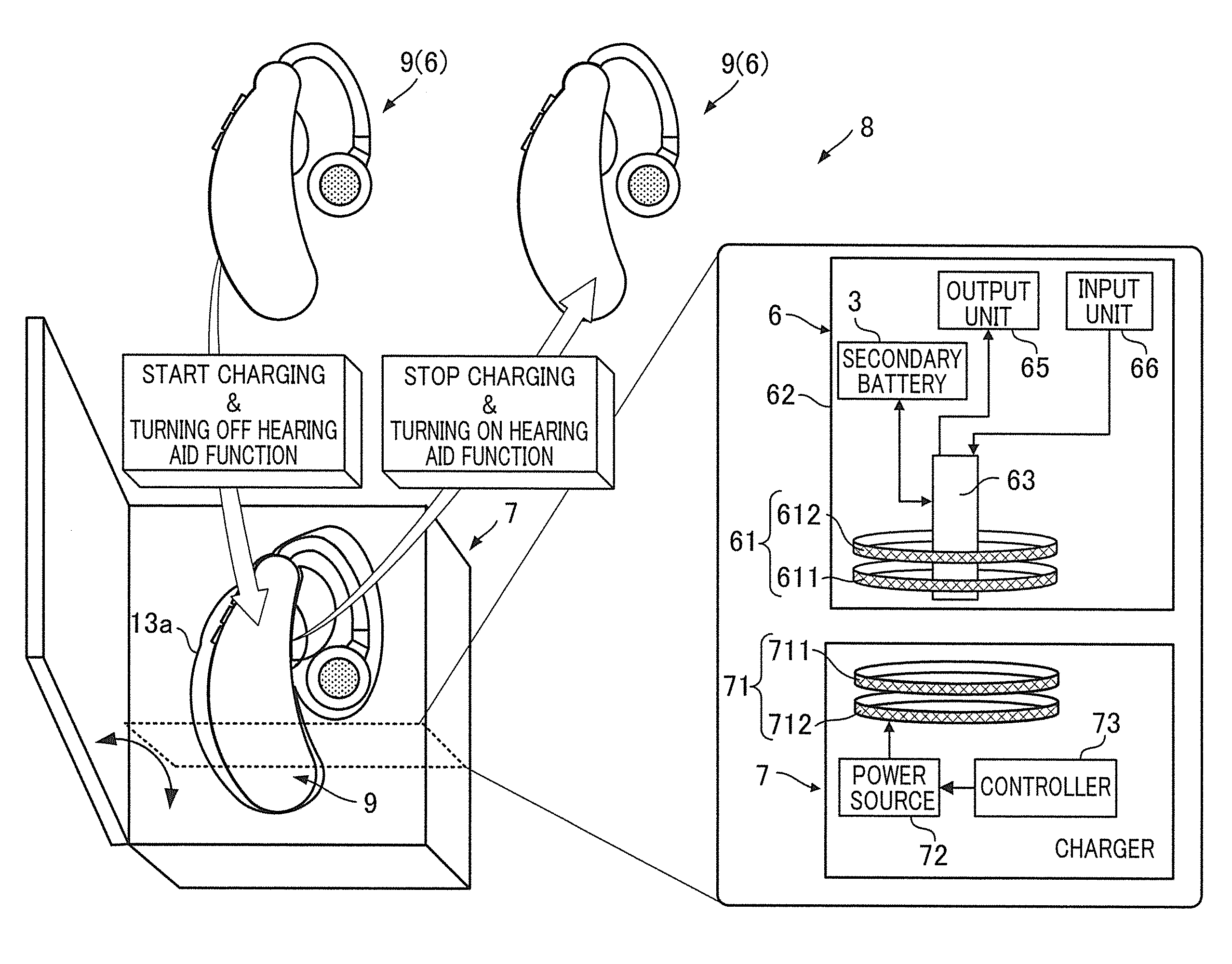
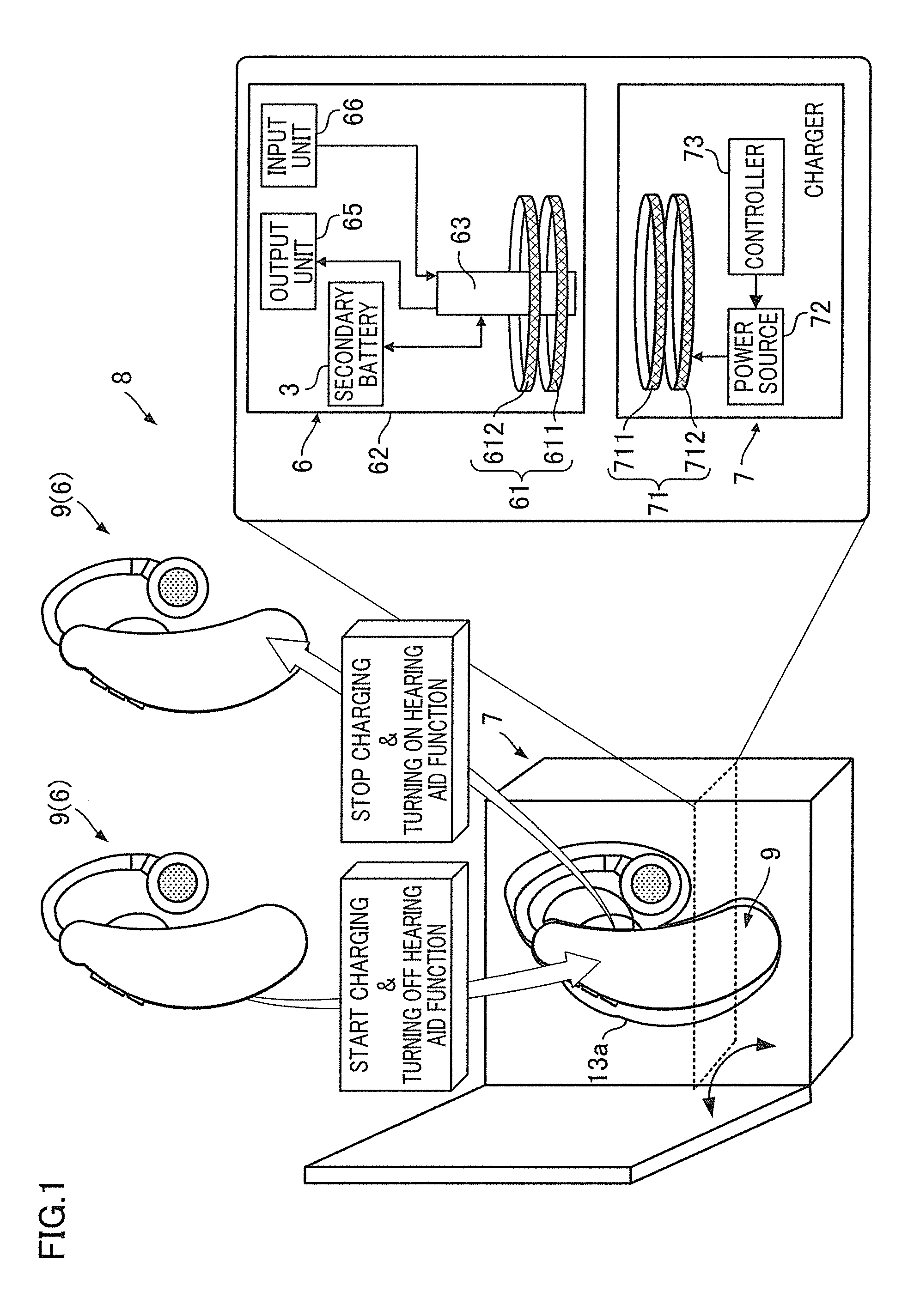
[0124]Embodiment 1 has described the arrangement having the function of charging the secondary battery 3 while stopping the power supply to the driving component 5 upon the attachment of the portable device 6 to the charger 7 and the function of stopping the charging of the secondary battery 3 while supplying power to the driving component 5 upon the detachment of the portable device 6 from the charger 7. For example, the charging system 8 shown in FIG. 1 is arranged to start the charging and to turn off of the hearing aid function upon the attachment of the ear-hook hearing aids 9 to the charger 7, and to stop the charging and to turn on the hearing aid function upon the removal of the ear-hook hearing aids 9 from the charger 7.

[0125]The portable device 6, the charging system 8, and the power source circuit substrate 1, however, are not limited to the arrangement having the functions above. As shown in FIG. 8, the portable device 6 may be arranged to have a function of charging the...

embodiment 3

[0159]Embodiment 1 and Embodiment 2 deal with the power source circuit substrate 1 and the portable device 6 in which, as shown in, for example, FIG. 2, the state of the transformation unit (processing unit) 124 is switched from the operation state to the stopped state only when the input of the power to the charging unit 112 is carried out. The disclosure, however, is not limited to this arrangement. That is to say, the power source circuit substrate 1 and the portable device 6 may be arranged such that the transformation unit (processing unit) 124 and the driving component 5 are switched from the operation state to the stopped state only when the charging of the secondary battery 3 by the charging unit 112 is carried out. It is noted that the transformation unit 124 is an example of the processing unit, and the processing unit encompasses all types of circuits executing signal processing.

[0160]To be more specific, as shown in FIG. 14, the power source circuit substrate 1 includes ...


PUM


Abstract

A portable device is arranged to include a secondary battery, a driving component driven by charged power of the secondary battery, a charging unit configured to charge the secondary battery by outside power, a transformation unit (processing unit) configured to output the charged power of the secondary battery at a driving voltage of the driving component, a detection unit configured to detect the input of the outside power to the charging unit, and a switching controller configured to switch the state of the transformation unit from an operation state to a stopped state only when the input of the outside power to the charging unit is detected by the detection unit.

Description

TECHNICAL FIELD[0001]The present invention relates to a portable device, a charging system, and a power source circuit substrate, which have a function of not allowing a driving component to operate when a secondary battery is being charged.BACKGROUND[0002]In known arrangements, in order to prevent a driving component (which is driven by power of a secondary battery) from operating while the secondary battery is being charged (to prevent unnecessary discharge and malfunction), a manual on-off mechanism employing a pushbutton (e.g., PTL 1) or an automatic on-off mechanism employing a mechanical contact (e.g., PTL 2) has been used to stop the operation of the driving component during the charging.[0003]When the mechanism above is employed, another action is required in addition to the charging operation, in order to stop the operation of the driving component during the charging. This is not disadvantageous when, for example, the driving component is a mobile phone, because the mobile...

Claims


Application Information

Patent Timeline
Patent Type & Authority Applications(United States)
IPC IPC(8): H02J7/00H02J7/04
CPCH02J7/04H02J7/025H02J7/0068H02J7/0044H02J50/80H02J50/12H02J7/0042H02J50/90
Inventor HATANAKA, TAKEZOTSUDA, HISASHI
Owner HIMPP
Why Eureka
Try Eureka