Ventilating insole structure
a technology of insole structure and ventilation, which is applied in the direction of uppers, insoles, bootlegs, etc., can solve the problems of high cost, difficult to guide external air into the shoe, complicated structure, etc., and achieve the effect of keeping the insole dry and clean, cost-effective and convenient us
- Summary
- Abstract
- Description
- Claims
- Application Information
AI Technical Summary
Benefits of technology
Problems solved by technology
Method used
Image
Examples
second embodiment
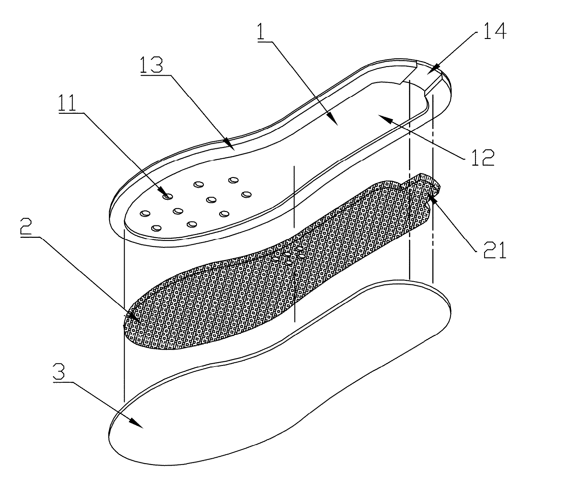
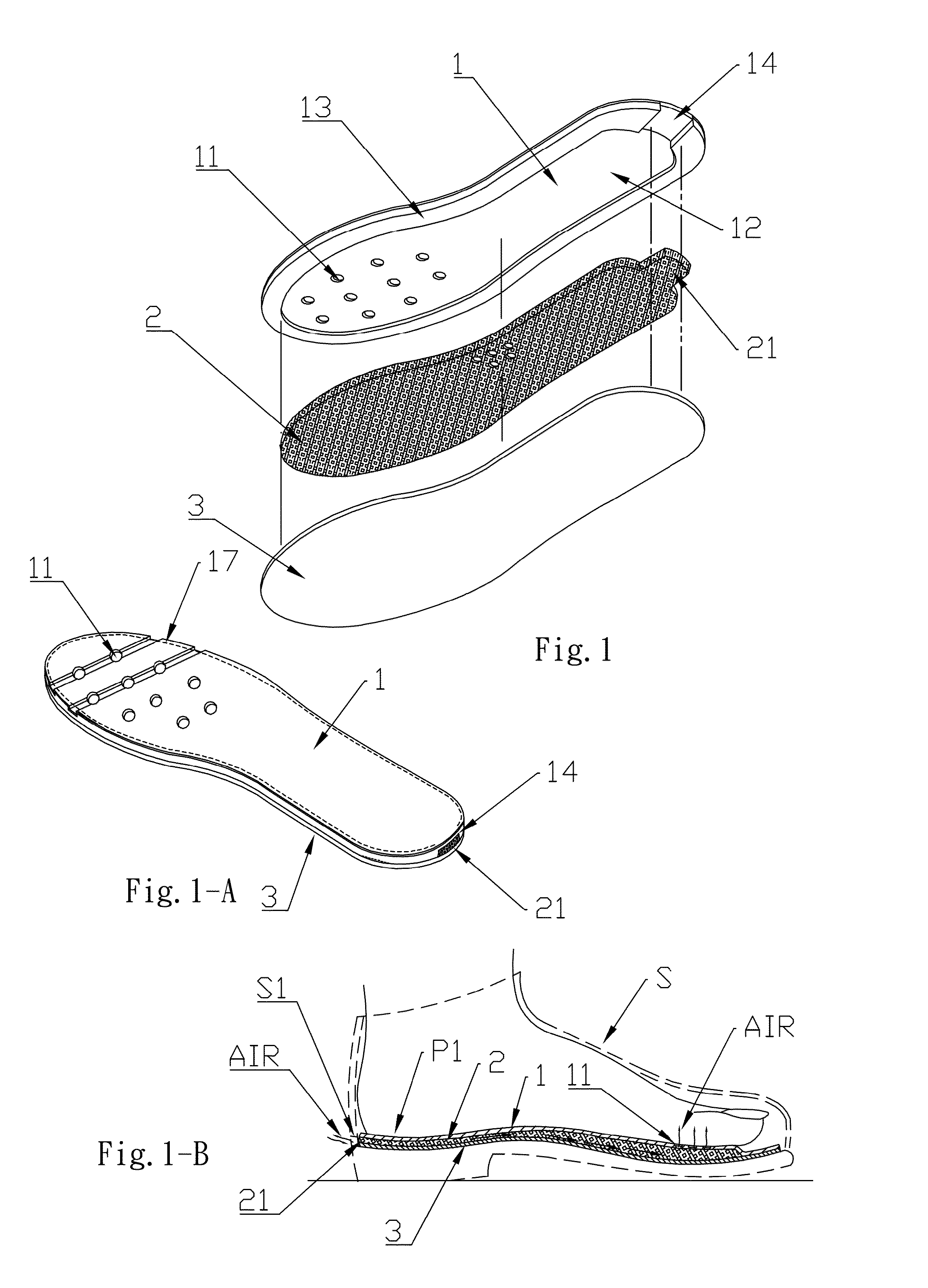
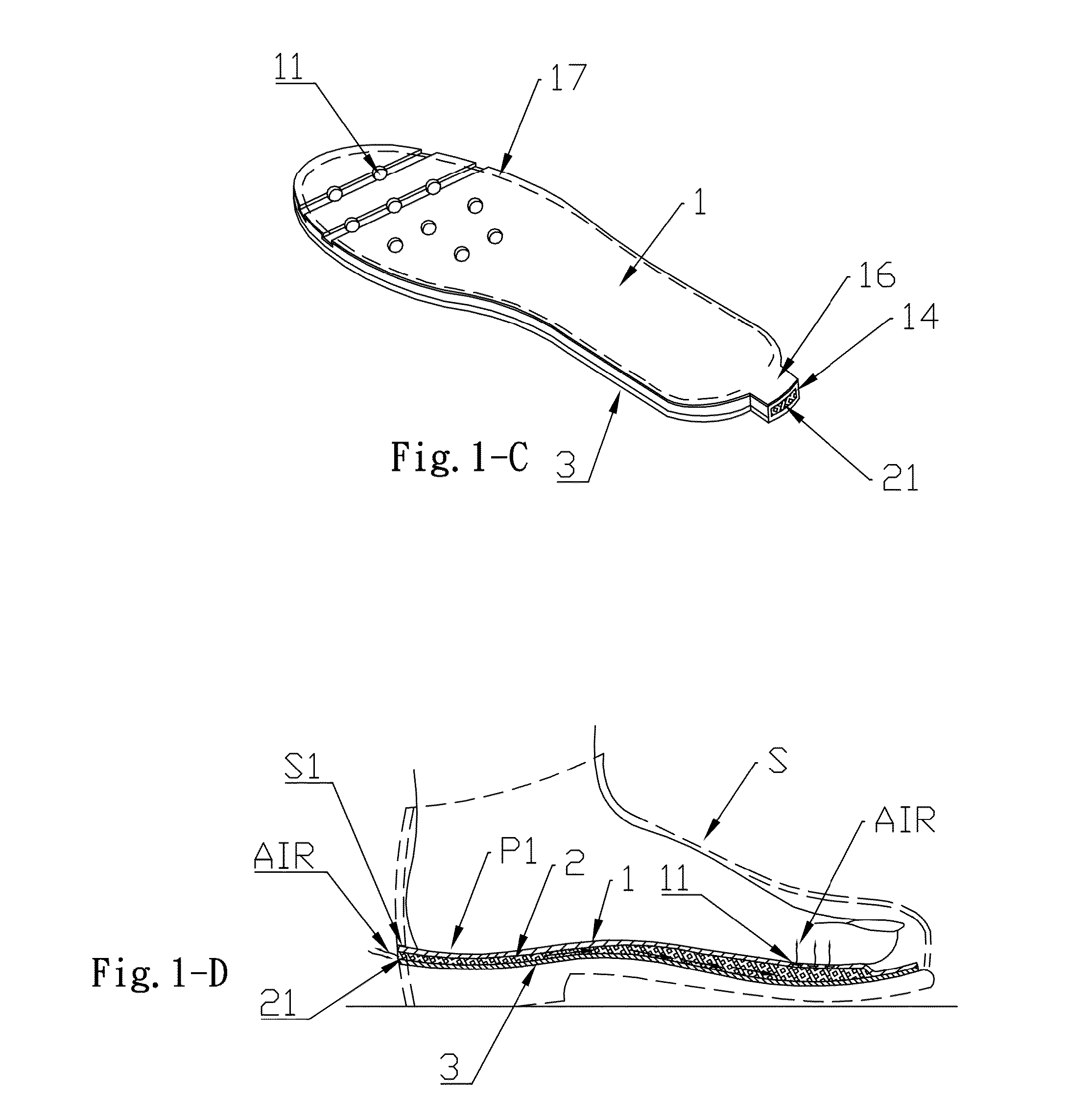
[0036]FIG. 3, FIG. 3-A, and FIG. 4 show the present invention. The second embodiment is substantially similar to the first embodiment with the exceptions described hereinafter. The circumferential wall 13, 13A close to the heel portion of the upper insole 1, 1A, is provided with one or a plurality of notches 15, 15A configured to receive an air guide pipe 4 therein. The air guide pipe 4 corresponds in number and in shape to the notch 15, 15A for the rear end of the foam pad 2 to extend out rearward. The air guide pipe 4 is to prop up the upper insole 1, 1A and the lower insole 3, 3A at the notch 15, 15A for the air between the upper and lower insoles to enter and exit so as to achieve an air change effect.
[0037]The bottom of the heel portion of the shoe S is formed with an air outlet S2 corresponding to the notch 15, 15A. The air guide pipe 4 extends outward to be fitted in the air outlet S2. A distal end of the air guide pipe 4 can extend out of the shoe S to circulate the air for ...
third embodiment
[0038]FIG. 5, FIG. 5-A, and FIG. 6 show the present invention. The third embodiment is substantially similar to the second embodiment with the exceptions described hereinafter. The circumferential wall 13, 13A close to the heel portion of the upper insole 1, 1A, is provided with one or a plurality of notches 15, 15A configured to receive a converting pipe 5 therein. The converting pipe 5 corresponds in number to the notch 15, 15A for the rear end of the foam pad 2 to extend out rearward. The converting pipe 4 is to prop up the upper insole 1, 1A and the lower insole 3, 3A at the notch 15, 15A for the air between the upper and lower insoles to enter and exit so as to achieve an air change effect. Wherein, a distal end of the converting pipe 5 is connected with a socket 61 of an L-shaped sleeve 6 to form a bent and extendable air passage. The sleeve 6 can be hidden at the inner side of the shoe S. A distal end of the sleeve 6 can extend out of the shoe. The converting pipe 5 and the L...
fourth embodiment
[0039]FIG. 7 and FIG. 7-A show the present invention. The fourth embodiment is substantially similar to the first embodiment with the exceptions described hereinafter. The foam pad 2 is fitted in the accommodation trough 12 of the upper insole 1 by the circumferential wall 13, and then attached to a top surface of a sole 7, such that the foam pad 2 is sandwiched and positioned between the upper insole 1 and the sole 7. The bottom of the heel portion of the sole 7 is formed with an air outlet 71 corresponding to the foam lug 21 extending from the rear end of the foam pad 2, such that the foam lug 21 can extend outward for the air to enter and exit so as to achieve an air change effect. The sole 7 is combined with the upper insole 1 and the foam pad 2 having the foam lug 21 to constitute a simple and ventilating sole structure.
[0040]FIG. 8 and FIG. 9 show a fifth embodiment of the present invention. The foam pad 2 is fitted in the accommodation trough 12, 12A of the upper insole 1, 1A...
PUM
 Abstract
Description
Claims
Application Information
 - R&D
- Intellectual Property
- Life Sciences
- Materials
- Tech Scout
- Unparalleled Data Quality
- Higher Quality Content
- 60% Fewer Hallucinations
Browse by: Latest US Patents, China's latest patents, Technical Efficacy Thesaurus, Application Domain, Technology Topic, Popular Technical Reports.
© 2025 PatSnap. All rights reserved.Legal|Privacy policy|Modern Slavery Act Transparency Statement|Sitemap|About US| Contact US: help@patsnap.com


