Configurable Intervertebral Implant

a technology of intervertebral implants and implant plates, which is applied in the field of medical devices, can solve the problems of reducing the height of the disc space, affecting the function of the disc, so as to maximize the effectiveness of the surgical device, quick and easy manipulation of the implant, and easy conversion of magnetic resonance imaging

Active Publication Date: 2016-01-14
MIGHTY OAK MEDICAL INC
View PDF5 Cites 42 Cited by
  • Summary
  • Abstract
  • Description
  • Claims
  • Application Information

AI Technical Summary

Benefits of technology

[0008]Intervertebral discs, which are located between endplates of adjacent vertebrae, normally stabilize the spine and distribute forces between the vertebrae and cushion vertebral bodies. The spinal discs may be displaced or damaged due to trauma, disease or aging. Displacement or damage to the intervertebral discs may result in nerve damage, pain, numbness, muscle weakness, and even paralysis. Furthermore, as a result of the normal aging processes, these discs dehydrate and harden, thereby reducing the disc space height and producing instability of the spine and decreased mobility.
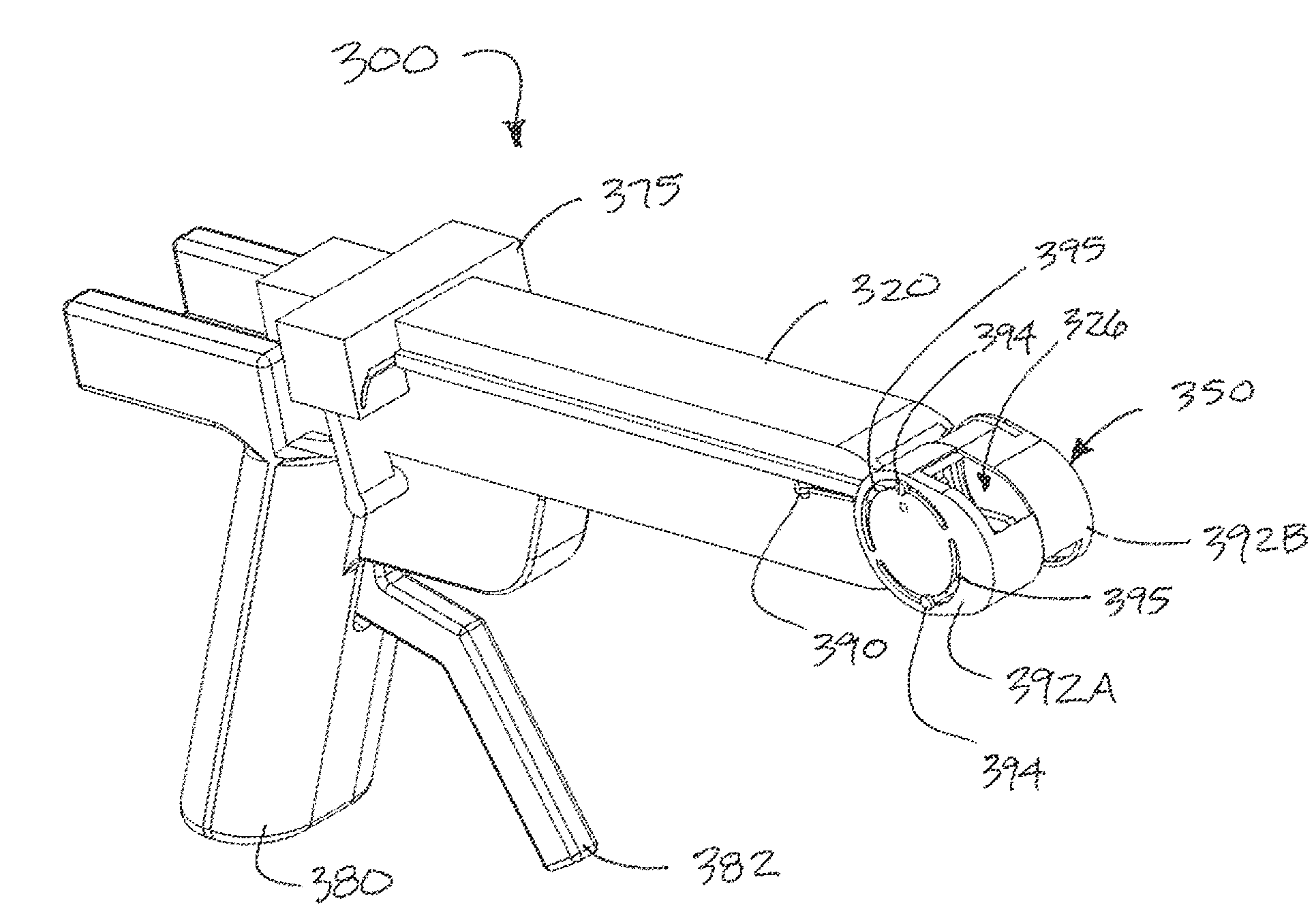
[0011]According to one aspect of the present disclosure, a surgical device is described which may be manipulated in various manners to accommodate delivery through a minimally invasive portal in one configuration and adjusted to a second configuration once placed in the intervertebral space. Varying embodiments described herein permit a surgeon or other medical professional to quickly and easily manipulate the implant to achieve one or more configurations as required for the particular approach and / or operation. The adjustable surgical devices described herein provide an advantage over the prior art, in particular by providing one or more adjustable features for maximizing the effectiveness of the surgical device, which in turn reduces the likelihood of misalignment, misplacement and subsequent mistake during the surgical procedure(s).
[0012]According to another aspect of the present disclosure, a surgical device is described which includes one or more adjustable features for achieving a desired outcome for a particular surgical procedure. More specifically, surgeons have the ability to readily convert magnetic resonance imaging (MRI) data or computed tomography (CT) data into a data set readable by computer-aided design (CAD) program and / or finite element modeling (FEM) program. This data may be used to create a surgical plan that accounts for unique anatomical variations and other constraints, and permits the surgeon to efficiently insert, place and manipulate the device or implant within an intervertebral space. Thus, the surgical device of one embodiment may be inserted in a first configuration and then adjusted to a second configuration that allows the structural aspects of the surgical device to be accurately aligned with the structural needs of the patient.
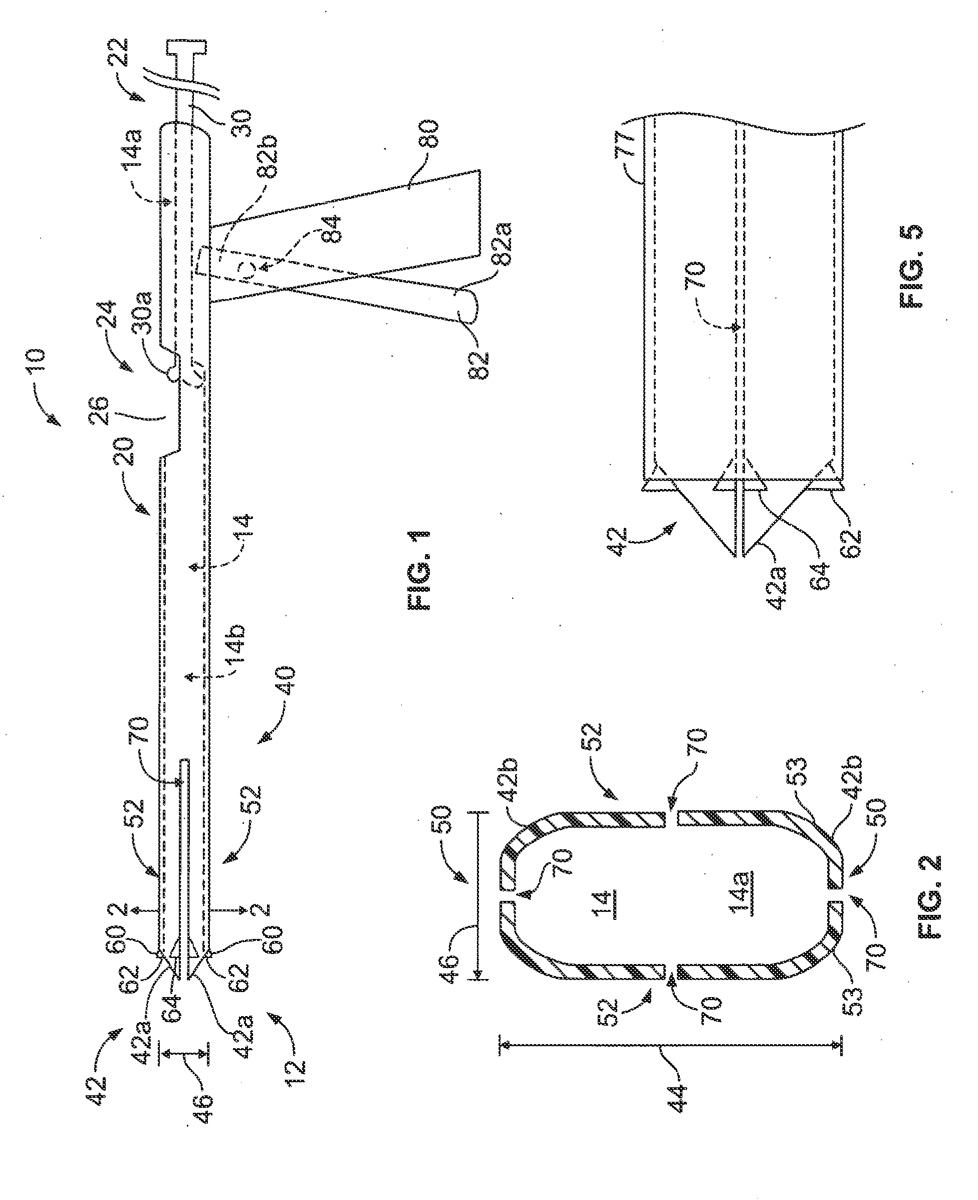
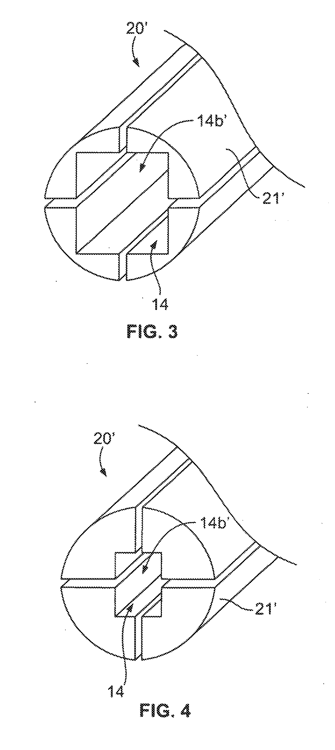
[0025]The access port also includes a distractor with at least one distractor block sized to move through the cannula bore. the distractor block are adapted to move the distractor plates to an expanded position such that the distraction of the adjacent vertebrae is increased to a second distance that is greater than the width of the cannula. The access port further includes a shaft with a second bore, the second bore adapted to guide an implant to the intervertebral space, the expansion tube sized to fit within the cannula bore and move the distractor block radially beyond a width of the cannula body to increase the distraction of the adjacent vertebrae to a third distance. In one embodiment, the distractor includes one distractor block. In another embodiment, the distractor includes two distractor blocks. In still another embodiment, after the distractor block is in the radially extended position, a second distractor with at least one second distractor block is inserted in the cannula bore. Thereafter, the expansion tube can be used to move the second distractor block radially beyond the cannula body to increase the distraction to a fourth distance greater than the third distance.
[0050]In some embodiments, the surgical device comprises a barrel that permits a user to at least partially distract patient tissue and / or dilate the barrel for use of the surgical device in a minimally invasive surgical procedure.

Problems solved by technology

The spinal discs may be displaced or damaged due to trauma, disease or aging.
Displacement or damage to the intervertebral discs may result in nerve damage, pain, numbness, muscle weakness, and even paralysis.
Furthermore, as a result of the normal aging processes, these discs dehydrate and harden, thereby reducing the disc space height and producing instability of the spine and decreased mobility.
While it is desirable in these approaches to place one or more implants into a single disc space so that the load of the spinal column is evenly distributed, implants are often designed to facilitate placement through a single approach; however, implants designed for a single approach sacrifice key implant features necessary to accomplish the goals of the surgical procedure.
In addition, accurate placement, and subsequent manipulation of implants in the disc space has heretofore been extremely difficult, particularly in light of the complexity associated with prior art expandable implants.

Method used


Image

  • Configurable Intervertebral Implant
  • Configurable Intervertebral Implant
  • Configurable Intervertebral Implant

Examples


Embodiment Construction

[0192]For the purposes of promoting an understanding of the principles of the present invention, reference will now be made to the embodiments illustrated in the drawings, and specific language will be used to describe the same. It will nevertheless be understood that no limitation of the scope of the invention is intended thereby. Any alterations and further modification in the described processes, systems, or devices, and any further applications of the principles of the invention as described herein are contemplated as would normally occur to one skilled in the art to which the invention relates.

[0193]By way of example but not limitation, the present disclosure will be described most often in connection with a minimally-invasive approach to the disc space, such as by way of example a transforaminal approach. However, it is expressly understood that with any of the approaches described in the Summary above, it is often difficult to prepare the proper locations in the disc space to...


PUM


Abstract

The present disclosure relates to a surgical device, such as a surgical implant, which may be used in several types of procedures. More specifically, the present disclosure relates to implants for use in an anterior, posterior, posterior lateral or direct lateral approach to the disc space. The surgical device may be manipulated in various manners to accommodate delivery through a minimally invasive portal in one configuration and adjusted to a second configuration once placed in the intervertebral space. A delivery system for placing the surgical device in a body is also disclosed.

Description

CROSS-REFERENCE TO RELATED APPLICATIONS[0001]This application is a continuation-in-part of U.S. patent application Ser. No. 14 / 286,639, filed May 23, 2014, and claims priority under 35 U.S.C. §119(e) to U.S. Provisional Application No. 62 / 052,790, filed Sep. 19, 2014. U.S. patent application Ser. No. 14 / 286,639 is a continuation-in-part of U.S. patent application Ser. No. 12 / 434,328, filed May 1, 2009, which in turn claims priority to U.S. Provisional Application No. 61 / 051,036, filed on May 7, 2008. Each of these applications is incorporated herein by reference in its entirety.FIELD OF THE INVENTION[0002]The present disclosure relates to the field of medical devices and is generally directed towards a device for insertion between two adjacent vertebral bodies and to devices for distracting two or more anatomical features. The device may be manipulated in various manners to accommodate delivery through a minimally invasive portal in one configuration and adjusted to a second configu...

Claims


Application Information

Patent Timeline
Patent Type & Authority Applications(United States)
IPC IPC(8): A61B17/02A61B17/70A61F2/44A61F2/46
CPCA61B17/025A61B17/7077A61F2/4455A61F2/4601A61F2210/0014A61B2017/0256A61F2002/448A61F2002/4627A61F2/4611A61B17/3468A61B17/56A61B17/58A61B17/70A61B17/7059A61B17/8009
Inventor FREY, GEORGEVOELKEL, CALEBKANA, GREGLAI, GEOFF
Owner MIGHTY OAK MEDICAL INC
Why Eureka
Try Eureka