
Elongated Gripping Device

Inactive Publication Date: 2016-01-14
TOWNER JOSEPH
View PDF2 Cites 0 Cited by
  • Summary
  • Abstract
  • Description
  • Claims
  • Application Information

AI Technical Summary

Benefits of technology

The present invention is for an elongated gripping device that can be used for grasping and moving logs and objects of different shapes and sizes. This device is made from economical and durable materials. Its technical effects are better user experience and versatility in usage.

Problems solved by technology

Thus, Pankratz discloses a device for grasping logs, but fails to disclose a device having an outer shaft with one or more prongs, and inner shaft with one or more prongs, wherein the user can actuate the device by rotating a handle thereon.
Thus, Stright fails to disclose a device having an outer shaft with prongs thereon and an inner shaft with prongs thereon, wherein the prongs can be used to grasp an object by rotating a handle on an end of the device.
Thus, Bernier discloses fireplace tongs and fails to disclose a device having an inner and outer shaft each having prongs thereon for grasping a log or other object.
Thus, Wolff et al. does not disclose an elongated gripping device for grasping logs within a fire that includes an inner shaft disposed within an outer shaft.
Thus, while Pronesky et al. discloses a grasping device, Pronesky does not disclose a device having an inner and outer shaft with prongs thereon, wherein the prongs are movable by rotating the handle thereof.
However, these devices fail to disclose a device having an inner shaft positioned within an outer shaft, wherein the inner shaft can rotate therein.
This arrangement saves space and conceals the moving portions of the device.
Other such devices provide only a trigger mechanism for opening and closing the jaws, limiting the degree to which the jaws can be opened.

Method used


Image

  • Elongated Gripping Device
  • Elongated Gripping Device
  • Elongated Gripping Device

Examples


Embodiment Construction

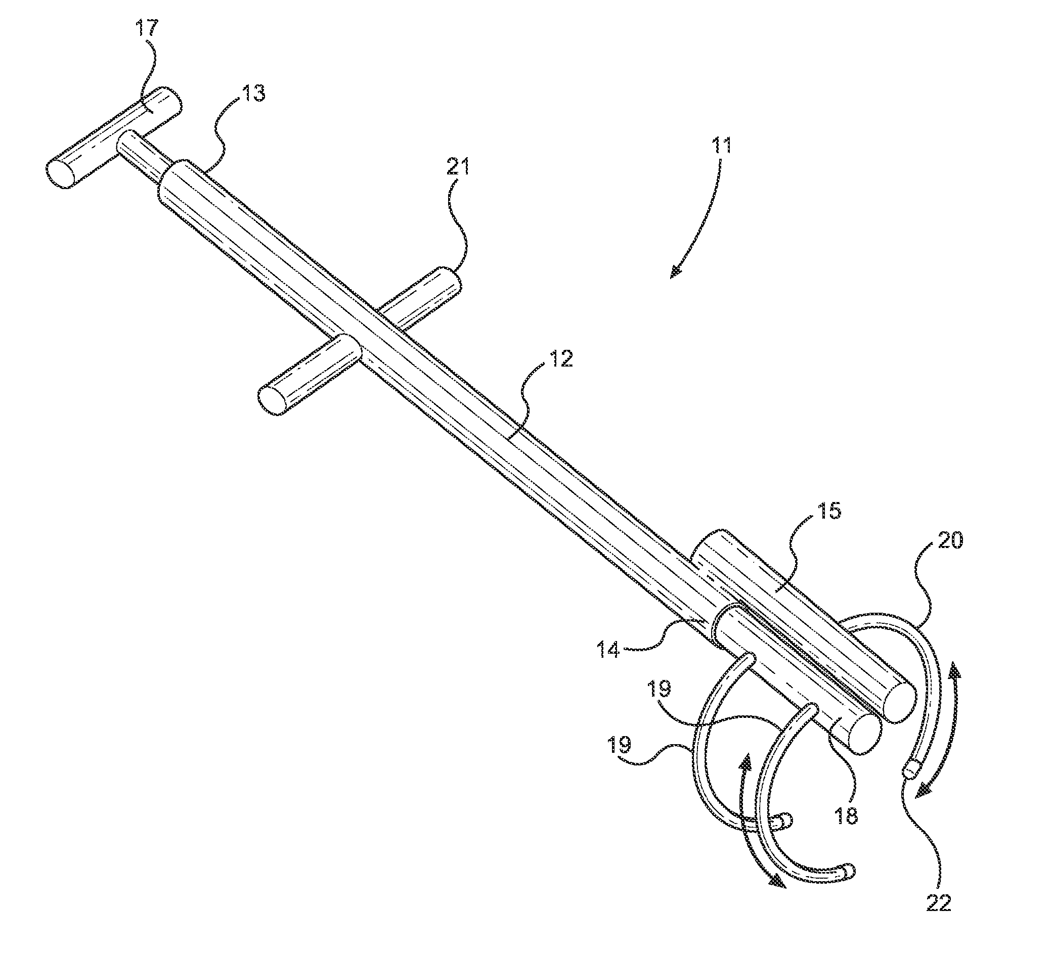
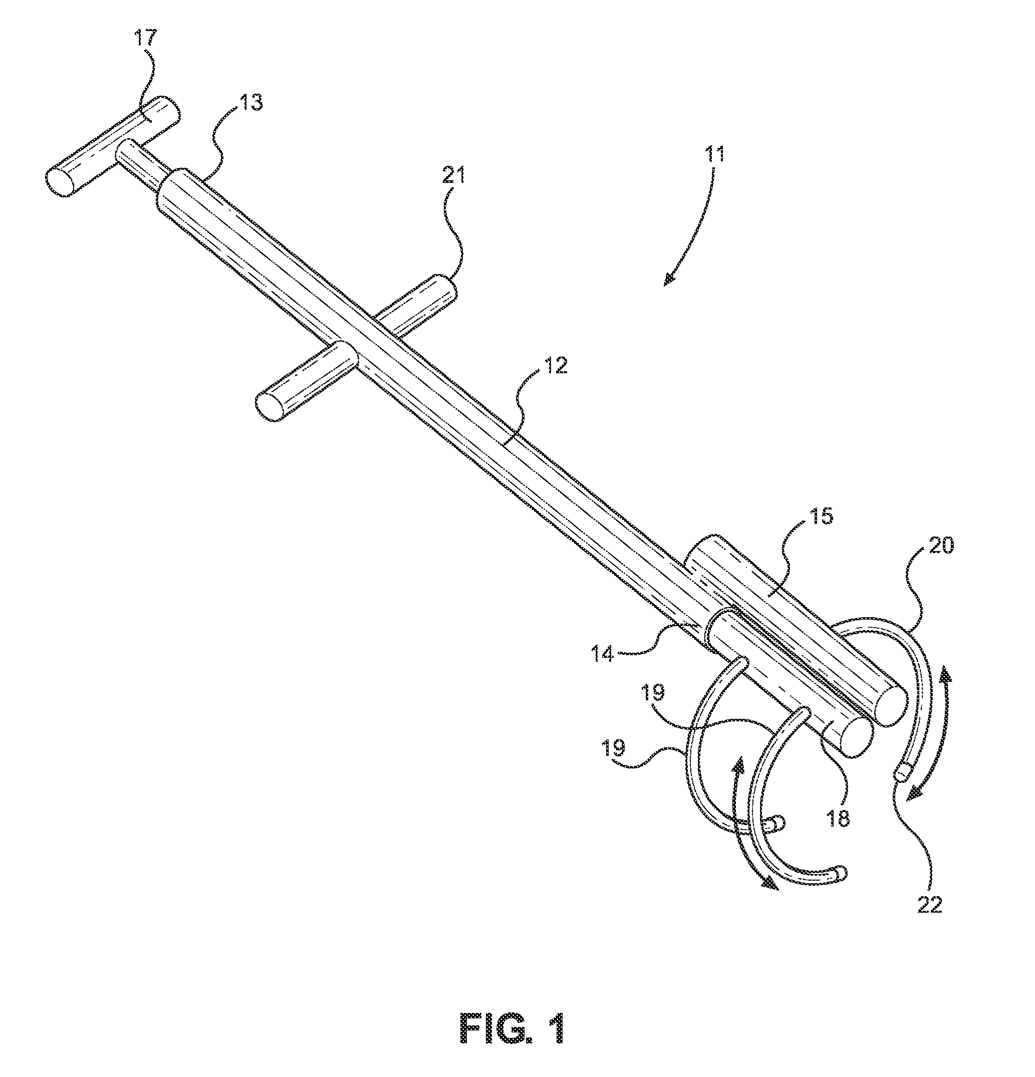
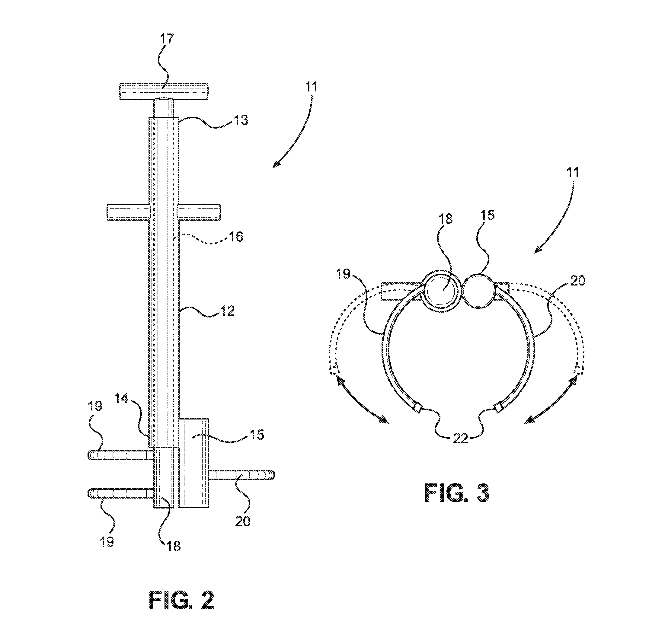
[0024]Reference is made herein to the attached drawings. Like reference numerals are used throughout the drawings to depict like or similar elements of the elongated gripping device of the present invention. For the purposes of presenting a brief and clear description of the present invention, the preferred embodiment will be discussed as used for grasping objects, such as logs within a fire, for the purpose of lifting or transporting the objects. The figures are intended for representative purposes only and should not be considered to be limiting in any respect.

[0025]Referring now to FIG. 1, there is shown a perspective view of the gripping tool of the present invention. The present invention provides a gripping tool 11 having an elongated outer shaft 12 with a hollow interior volume, a first end 13, and a second end 14. The outer shaft 12 is substantially linear and is preferably cylindrical. The outer shaft 12 is preferably composed of a strong, durable material that will not be ...


PUM


Abstract

An elongated gripping device for grasping objects, and particularly useful for moving and adjusting logs used to build a fire. The elongated gripping device includes an elongated outer shaft having an extension shaft on an end thereof. The extension shaft includes one or more prongs on an end thereof, disposed transversely to the extension shaft. The elongated gripping device further includes an elongated inner shaft extending through the outer shaft, and having a handle at a first end thereof. The inner shaft further includes one or more prongs on the second end thereof that are arranged transversely to the inner shaft. The prongs on the inner shaft and on the extension shaft oppose one another so as to form a claw-like structure that can be used to grasp objects of various shapes and sizes by rotating the handle to actuate the prongs.

Description

CROSS REFERENCE TO RELATED APPLICATION[0001]This application claims the benefit of U.S. Provisional Application No. 62 / 021,743 filed on Jul. 8, 2014. The above identified patent application is herein incorporated by reference in its entirety to provide continuity of disclosure.BACKGROUND OF THE INVENTIONField of the Invention[0002]The present invention relates to an elongated gripping device. More specifically, the present invention provides a gripping device for moving pieces of wood within a fire. The present invention includes an elongated shaft having opposing prongs on an end thereof that be actuated by means a rotatable handle on the opposite end of the elongated shaft, so that the prongs can be used to grasp and lift various objects.[0003]When building and sustaining a fire, it is often necessary to adjust the burning pieces of wood within the fire. Wood is consumed as the fire burns, and the remaining pieces of wood may shift within the fire. If the fire is not constructed p...

Claims


Application Information

Patent Timeline
IPC IPC(8): F24B15/10B25J1/04
CPCB25J1/04F24B15/10
Inventor TOWNER, JOSEPH
Owner TOWNER JOSEPH
Learn More