[0037]To facilitate understanding, identical reference numerals have been used, where possible, to designate identical elements that are common to the figures.
DETAILED DESCRIPTION
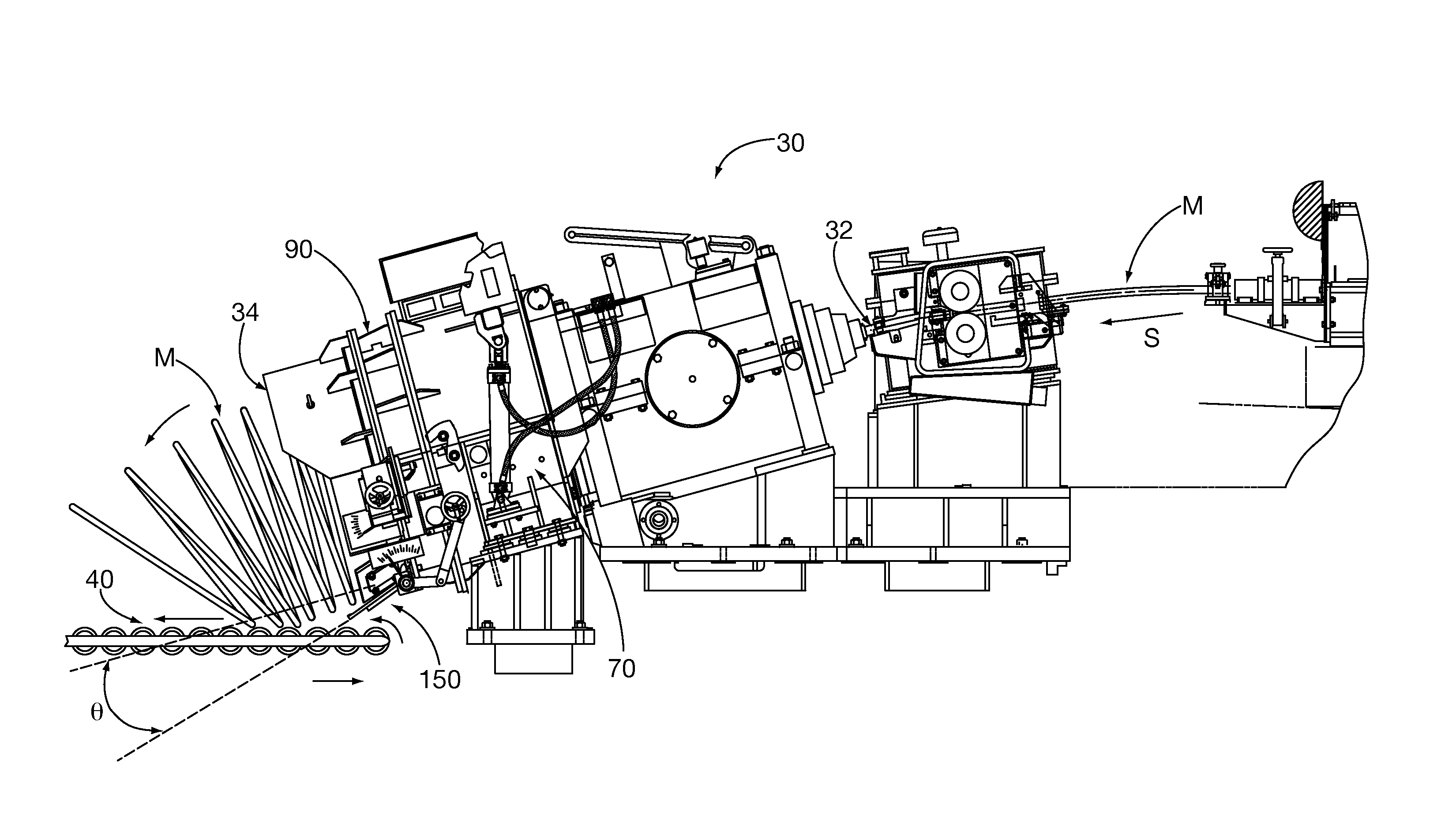
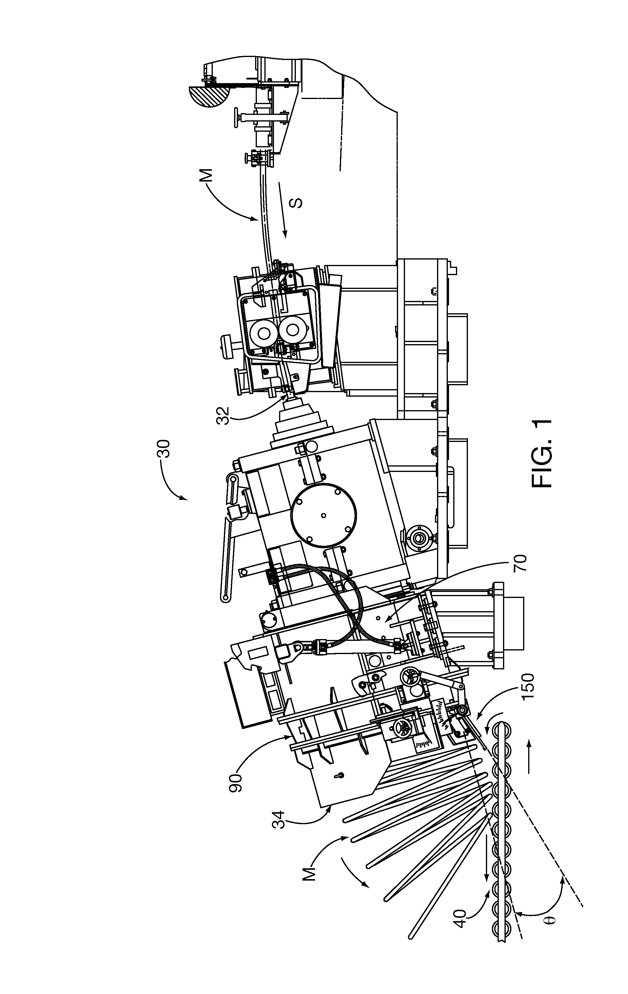
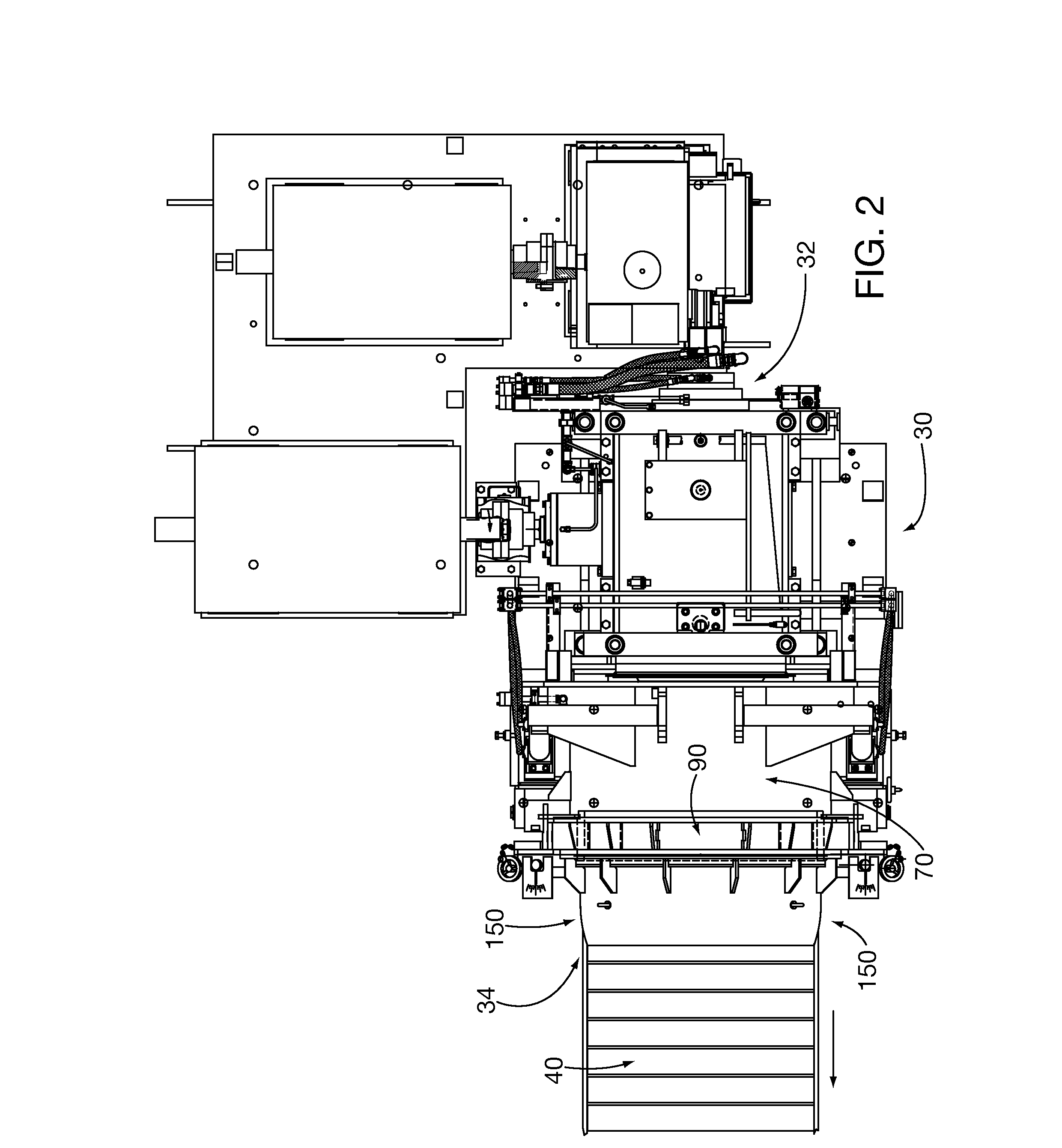
[0038]After considering the following description, those skilled in the art will realize that the teachings of the present invention can be utilized in rolling mill coil-forming apparatus laying heads and more particularly to laying head elongated transport path pipes or other equivalent elongated structures for laying heads. Aspects of the present invention facilitate longer laying head path service life so that more tons of elongated material can be processed by the laying head before preventative maintenance replacement. For example, it is possible to increase the laying head elongated material processing speed so that more tons of elongated material can be processed in a production shift without undue risk of laying head path/pipe failure. A portion or the entire elongated structure is formed from modular, selectively replaceable components. The fabricated modular structures facilitate replacement of zones within the elongated path that are subject to greater wear than the rest of the structure. The fabricated modular structures also facilitate formation and reconfiguration of zones within the component, such as including by way of example wear-resistant zones, material transport guide structures and friction reducing zones.
[0039]Laying Head System Overview
[0040]Referring generally to FIGS. 1-4, the coil-forming apparatus laying head system 30 coils rolled elongated material M, such as for example hot rolled steel. Elongated material M that is advancing at speed S, which may be as high as or greater than approximately 500 feet/second (150 m/sec), is received in the laying head system 30 intake end 32 and discharged in a series of continuous coil loops at the discharge end 34, whereupon the coils are deposited on a conveyor 40.
[0041]The laying head system 30 comprises a rotatable quill 50, a path 60 and a pipe path support 70. The path 60 defines a hollow elongated cavity to enable transport of the material M. Aspects of the present invention allow the path to comprise a laying head pipe; indeed, the path 60 may occasionally be referred to as a laying head pipe herein.
[0042]The quill 50 can have a generally horn shape that is adapted to rotate about an axis. The path 60 has a generally helical axial profile of increasing radius, with a first end 62 that that is aligned with the rotational axis of quill 50 and receives elongated material M. The path 60 has a second end that is spaced radially outwardly from and generally tangential to the quill 50 rotational axis and thus discharges the elongated material generally tangentially to the periphery of the rotating quill. The path 60 is coupled to a pipe support 70 that is in turn coupled coaxially to the quill 50, so that all three components rotate synchronously about the quill rotational axis. The quill 50 rotational speed can be selected based upon, among other factors, the elongated material M structural dimensions and material properties, advancement speed S, desired coil diameter and number of tons of elongated material that can be processed by the laying head pipe without undue risk of excessive wear. FIG. 5 shows conventional laying head path/pipe 60 wear zones 66, 68 in which the pipe interior is subjected to relatively higher wear rates than other portions of the pipe. Aspects of the present invention address the higher wear rates by locally hardening the zones 66, 68 and other portions or all other desired zones. In an embodiment, the entire or equivalent elongated structure can be hardened by application of aspects of the present invention.
[0043]As illustrated, as elongated material M is discharged from the second end 64, it is directed into a ring guide 80 having guide rim segments 82 into which are formed a guide trough channel 84 having a helical pitch profile, such as that described in commonly owned U.S. Pat. No. 6,769,641. As the elongated material M is advanced through the ring guide 80 it is continued to be conformed into a continuous loop helix.
[0044]As described in the '641 patent, the segmented ring guide enables relatively easy reconfiguration of the ring guide helical diameter to accommodate different elongated materials by changing the rim segments 82 without disassembling and replacing the entire ring guide 80.
[0045]As previously noted, the elongated material M is configured into a continuous looped coil as it rides within the ring guide 80 helical trough channel 84. Ring guide 80 is coupled to the pipe support 70 and rotates coaxially with the quill 50. The helical trough 84 advancement rotational speed is harmonized with the elongated material M advancement speed S, so there is little relative linear motion speed between the two abutting objects and less rubbing wear of the trough 84 surfaces that contact the coiling material.
[0046]Stationary end ring 90 has an inner diameter that is coaxial with the quill 50 rotational axis and circumscribes the laying path/pipe 60 second end 62 as well as the ring guide 80. The end ring 90 counteracts centrifugal force imparted on the elongated material M as it is discharged from the laying head pipe 60 second end 62 and advances along the ring guide 80 helical trough channel 84 by radially restraining the material within the end ring inner diameter guide surface. High relative speed between the advancing elongated material M and the stationary end ring 90 causes rubbing wear on the end ring inner diameter guide surface.
[0047]Referring to FIG. 1, elongated material M that is discharged from the coil-forming apparatus laying head system 30 falls by gravity in continuous loops on roller conveyor 40, aided by the downwardly angled quill rotational axis at the system discharge end 34. Tripper mechanism 150 pivots about an axis abutting the distal axial side of the end ring 90 guide surface. That pivotal axis is generally tangential to the end ring 90 inner diameter guide surface about a pivotal range of motion θ. As is known, coiled material M coiling characteristics and placement on the conveyor 40 can be controlled by varying the pivotal angle θ.
[0048]Laying Head Path Structure Fabrication
[0049]Embodiments of the present invention include a rolling mill laying head path structure, for retention and transport of elongated materials in a laying head, so that the elongated material can be selectively coiled. A portion of the path structure, or the structure in its entirety, is constructed of modular replaceable sections or cartridges. In this way, only worn sections are replaced as necessary during laying head service scheduled maintenance without replacing the entire laying head path structure.
[0050]FIGS. 6-8 show a modular construction laying head path 960 that has a generally cylindrical outer profile conforming to known laying head pipes, for direct substitution in a known laying head such as the one shown in FIGS. 1-5. Laying head pipe 960 is a composite structure fabricated from modular subcomponents. The laying path 960 has a first steel pipe section 961A with an upstream intake end 962 and a second steel pipe section 961B that discharges elongated material from the laying head in coiled loops. The insert 970 is asymmetrical with a keyed and flanged male end portion 972 that mates with a complimentary flanged female portion 973 that is formed in the second steel pipe section 961B. The insert 970 also has a female portion 973 at its other axial end that mates with a keyed male end portion 972 formed on the first steel pipe section 961A. A circumferential clamp 990 circumscribes flanges of the respective axially mating male end portion 972 and female end portion 973. Other types of known mating end portions may be substituted for the ones shown in FIGS. 6-8.
[0051]FIGS. 9 and 10 show an alternative embodiment laying head path elongated hollow structure 1060 for coiling elongated material. The laying head elongated structure 1060 does not have a traditional known pipe-like profile but establishes a generally helical shaped elongated material internal transport path from its intake end 1062 to its discharge end 1064. The elongated structure 1060 has a replaceable modular cartridge section 1066 that includes an access compartment 1068 for insertion of a modular replacement cartridge 1070. As shown in FIG. 10 the replacement cartridge 1070 has flanged ends 1072, 1074 for engagement with respective ends of the access compartment 1068, and is sealed with cover 106.
[0052]FIG. 11 shows another alternative embodiment of a non-pipe-shaped laying head hollow cavity elongated structure 1160 that has an elongated material transport path with an intake end 1162 and discharge end 1164. The elongated structure 1160 is constructed with a plurality of axially adjoining segments 1171-1176, any one or more of which is selectively replaceable.
[0053]FIGS. 12 and 13 show another embodiment of the laying head path modular section or replacement cartridge 360 of the present invention that has a first intake end 362 with an annular retaining collar 362A. The laying head path modular section 360 is a composite structure fabricated from nested subcomponents including an outer steel pipe or tube 361 and an inner pipe or tube 363 formed from tungsten carbide tubing or tungsten carbide sintered to form a generally tubular hollow structure. The inner tube 363 has a continuous inner surface 363A for contact with elongated material that is transported through the laying head path. The inner surface 363A may be surface coated or treated to harden the surface or provide a friction reducing surface. An optional insulating high temperature grout layer 380 may be interposed between the outer pipe 361 and the inner pipe 363. While not shown in FIGS. 12 and 13 the modular section 360 may include coupling structure for coupling to adjoining segments or sections in a laying head path elongated structure, for example as shown in other embodiments herein.
[0054]The fabricated modular elongated laying path structures facilitate formation of zones within the components, such as including by way of example wear-resistant zones or friction reducing zones. Those zones can be formed during the modular cartridge fabrication process, such as by inserting pipes constructed of different material into each other or by abutting sections of different materials next to each other in a given layer. Portions of the modular components or entire components may be fabricated from various ferrous or non-ferrous materials, including ceramics, preferred examples comprising ferrous metals, nickel based alloys, cobalt based alloys and titanium based alloys, as well as deposited nano particle coatings of any of them. Different coating materials may be deposited in abutting relationship to form the laying path inner surface within a modular component. More specifically a component outer layer or pipe, if any, comprises any desired material or metal (steel often being a cost effective choice) or non-metallic structures, such as filament reinforced carbon fiber. The inner surface of a filament reinforced carbon fiber or other outer elongated path modular component may include an inner layer formed from a nano particle layer of non-ferrous material, such as stainless steel or tungsten carbide, deposited thereon, including abutting deposited layers of materials. The deposited nano layer(s) function(s) as the equivalent of a separate inner pathway structure. The modular component inner layer path forming structure may comprise ferrous or non-ferrous materials, including ceramic, nano particle material coatings, steel, or non-ferrous alloys such as stainless steel, tungsten carbide or so-called super alloys, such as for example Inconel®, Waspaloy® or Hastelloy®. Other non-ferrous metals may be substituted within modular components, comprising by way of example stainless steel, tungsten carbide, and so-called super alloys, such as for example Inconel®, Waspaloy® or Hastelloy®, ceramics or nano particle layers of the above. The inner surface that is in contact with the elongated material may be treated or coated (including nano particle coatings) to increase surface hardness, reduce friction or decrease thermal ablation. Alternatively one or more of the separate modules forming the entire elongated structure path/pipe can be constructed from a single homogeneous one of such non-ferrous materials of any desired dimensional circumferential profile inner or outer diameter and thickness. That homogeneous non-ferrous module can be nested inside or circumscribe one or more path layers to form a multilayer modular component of two or more layers. The multilayer modular component is then formed into any desired three dimensional profiles to form a laying head path elongated structure.
[0055]Although various embodiments, which incorporate the teachings of the present invention, have been shown and described in detail herein, those skilled in the art can readily devise many other varied embodiments that still incorporate these teachings.