Image processing method and device

An image processing and target image technology, applied in the computer field, can solve problems such as the spike coding function of the visual system of the human brain, and achieve the effect of promoting the construction

Pending Publication Date: 2020-11-13
INST OF MICROELECTRONICS CHINESE ACAD OF SCI
View PDF0 Cites 0 Cited by
  • Summary
  • Abstract
  • Description
  • Claims
  • Application Information

AI Technical Summary

Problems solved by technology

[0003] However, these systems are difficult to well realize

Method used


Image

  • Image processing method and device
  • Image processing method and device
  • Image processing method and device

Examples


Example

[0044] first embodiment

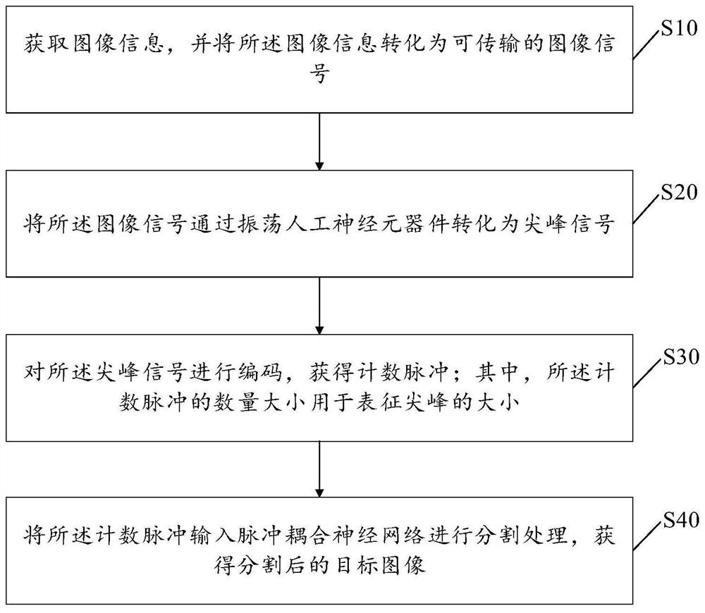
[0045] See figure 1 , shows a flow chart of an image processing method provided by the first embodiment of the present invention. The method includes:

[0046] Step S10: acquiring image information, and converting the image information into a transmittable image signal.

[0047] In step S10, the image information represents the captured or captured image. In this embodiment, image information can be collected by an image sensor, and the image sensor converts the light signal into a transmittable and storable image signal after collecting the light signal.

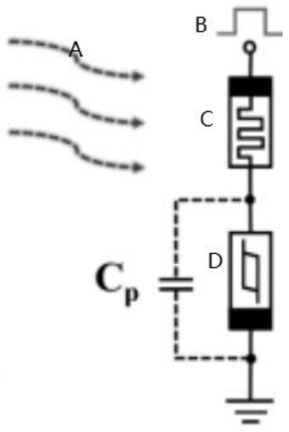
[0048] Step S20: converting the image signal into a spike signal through an oscillating artificial neuron device.

[0049] In step S20, the image signal can be converted into a spike signal by oscillating the artificial neuron device. In this implementation, the oscillating artificial neuron device can be connected in series with the image sensor to form a sensory neuron, such as figure 2 As...

Example

[0062] second embodiment

[0063] see Figure 5 , based on the same inventive concept, this embodiment provides an image processing device 300, the device 300 includes:

[0064] An acquisition module 301, configured to acquire image information, and convert the image information into a transmittable image signal;

[0065] A conversion module 302, configured to convert the image signal into a spike signal through an oscillating artificial neuron device;

[0066] An encoding module 303, configured to encode the peak signal to obtain a count pulse; wherein, the count pulse is used to represent the magnitude of the peak;

[0067] The segmentation module 304 is configured to input the counting pulses into the pulse-coupled neural network for segmentation processing, and obtain a segmented target image.

[0068] As an optional implementation manner, the encoding module 303 is specifically configured to:

[0069] converting the spike signal into a periodic electrical signal;

[...


PUM


Abstract

The invention discloses an image processing method and device, and the method comprises the steps: obtaining image information, and converting the image information into a transmittable image signal;converting the image signal into a peak signal through an oscillation artificial neural component; encoding the peak signal to obtain a counting pulse; wherein the number of the counting pulses is used for representing the size of a peak; and inputting the counting pulse into a pulse coupling neural network for segmentation processing to obtain a segmented target image. According to the invention,a peak coding function and a visual perception function in a human brain visual system can be realized.

Description

technical field [0001] The present invention relates to the field of computer technology, in particular to an image processing method and device. Background technique [0002] Human visual perception is an important part of the central nervous system, which endows the organism with the ability to process visual information. The human visual perception system mainly consists of sensory cells that perceive visual signals, such as photoreceptors, and processing units that convert the detected information into electrical peaks. The human visual perception system can simultaneously detect and process light information, and then transmit it to the various visual centers of the brain. This structure forms the basis of the combined sensing, preprocessing, and encoding capabilities of the human visual system. In recent years, researchers have developed some dynamic vision systems based on conventional image sensors and transistor pixel circuits. [0003] However, these systems are...

Claims


Application Information

Patent Timeline
IPC IPC(8): G06T3/00G06T7/10G06N3/067
CPCG06N3/0675G06T3/0012G06T2207/20084G06T7/10
Inventor 卢年端李泠吴全潭王嘉玮耿玓刘明
Owner INST OF MICROELECTRONICS CHINESE ACAD OF SCI
Why Eureka
Try Eureka