Air-floating-type base isolation device which uses a sliding expanding pipe shielding material

Active Publication Date: 2009-06-25
SANSEI AIR DANSHIN SYST LTD
View PDF8 Cites 3 Cited by
  • Summary
  • Abstract
  • Description
  • Claims
  • Application Information

AI Technical Summary

Benefits of technology

[0003]The present invention has an object of resolving the problems described above, and it aims to facilitate construction and make the checking and maintenance operations easier, while also allowing horizontal floating, wherever the center of gravity of a building lies.
[0004]In order to resolve the problems with known systems, internal operations are dispensed with when the top plate is constructed. This is done by prefabricating a groove into one plate, preferably the top plate. A sliding expanding pipe shielding material made of airtight material is inserted into the groove. The material is elastic and acts as an airtight material. The inside of the sliding expanding pipe shielding material is a cavity. Air is injected under pressure into the sliding expanding pipe shielding material, thereby expanding the expanding pipe shielding material so that an airtight effect between th

Problems solved by technology

But, it is difficult to fit the airtight material inside the top plate and bottom plate because of the nature of the construction and checki

Method used


Image

  • Air-floating-type base isolation device which uses a sliding expanding pipe shielding material
  • Air-floating-type base isolation device which uses a sliding expanding pipe shielding material
  • Air-floating-type base isolation device which uses a sliding expanding pipe shielding material

Examples


Example

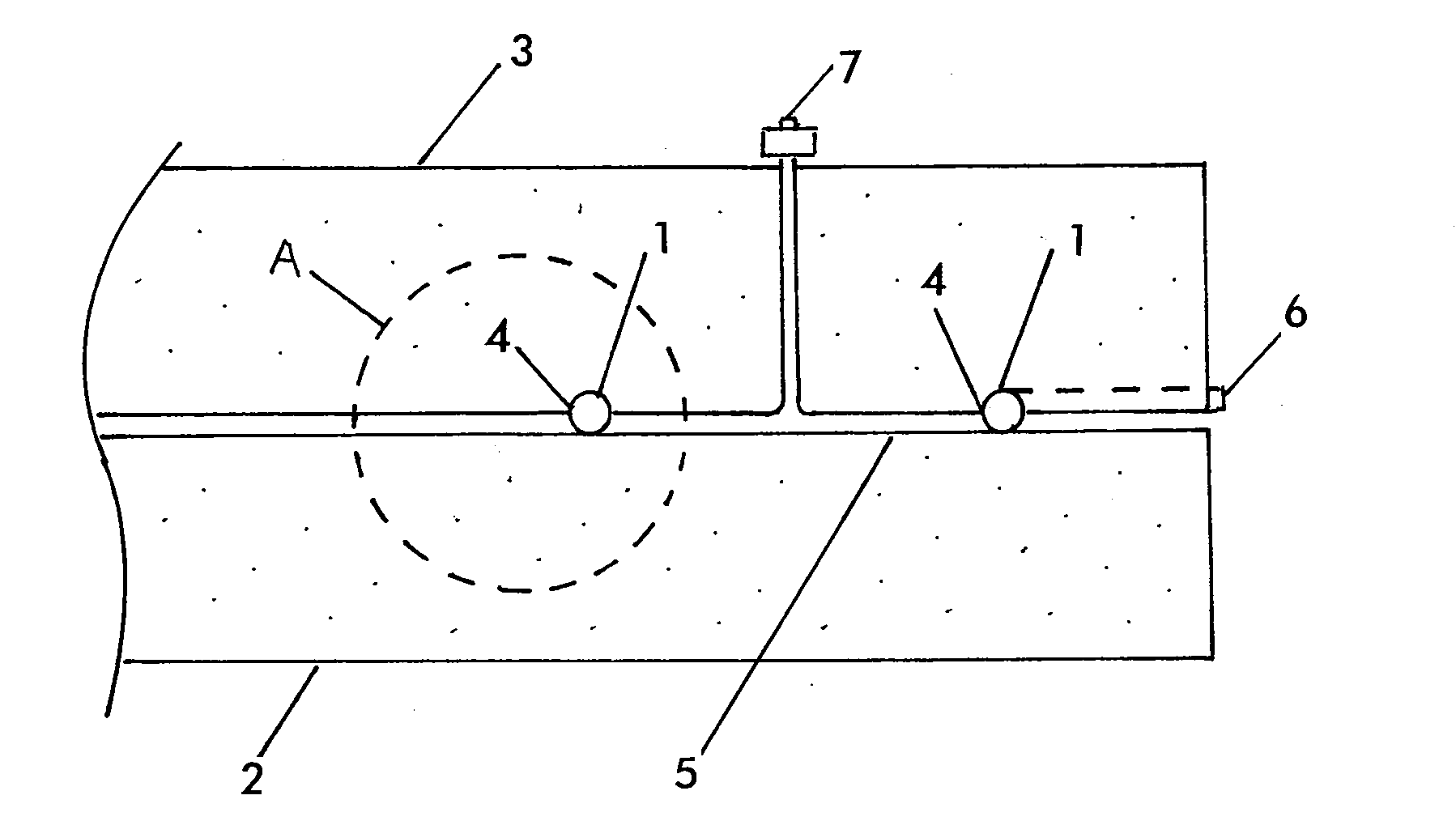
[0014]As shown in FIGS. 1A and 5, a groove 4 is formed in the underside of a top plate 3 for receiving the insertion of the sliding expanding pipe shielding material 1 which is made of airtight material. The material has an enclosed expandable tubular form. This embedded groove 4 employs a polyvinyl chloride or similar pipe in it. The groove has a semi-circular cross section, which is slightly wider than the shielding material. When the groove 4 is set in concrete, the inside of the groove forms a cavity. The groove or grooves may be formed anywhere over the area of the plate 3, enabling below described chambers 5 to be provided over as much of the area of the plate as desired. Although the grooves are shown formed in the top plate surface opposing the bottom plate, they may be formed in the top of the bottom plate. Other path guides for the material 1 may be provided, besides grooves.

[0015]The tubular sliding expanding pipe shielding material 1 is inserted from a sealed material in...


PUM


Abstract

An air-floating-type base isolation system having a plurality of air chambers defined and surrounded by a sliding expanding pipe shielding material. A groove in one plate receives a sliding expanding pipe of shielding material made of airtight material. A plurality of air pressure chambers are defined by placement of the grooves and shielding material at selected locations in the plate, so that the top plate can be allowed to float horizontally by adjustment of the pressure in the air pressure chambers, regardless of the position of the center of gravity of the building.

Description

BACKGROUND OF THE INVENTION[0001]The present invention relates to an air-floating-type base isolation system in which a bottom plate and a top plate constituting the foundations of a building are both used as part of an air pressure chamber, allowing the top plate to float directly above the bottom plate.PRIOR ART [0002]Known air-floating-type base isolation devices use a plate-type airtight material in order to maintain air pressure in an air pressure chamber. But, it is difficult to fit the airtight material inside the top plate and bottom plate because of the nature of the construction and checking, maintenance operations involved. Therefore, the airtight material is often only fitted to the outside and in a region which can be reached by hand from the outside. This means that the air pressure chamber is usually only provided around the periphery of a building. Problems may arise in terms of inclination due to the location of the center of gravity of the building.SUMMARY OF THE I...

Claims


Application Information

Patent Timeline
IPC IPC(8): E04H9/02
CPCE02D31/08E02D27/34
Inventor SAKAMOTO, SHOICHI
Owner SANSEI AIR DANSHIN SYST LTD
Why Eureka
Try Eureka