
Attachable tilling device

Inactive Publication Date: 2018-12-13
QUILLIN DAVID +1
View PDF1 Cites 1 Cited by
  • Summary
  • Abstract
  • Description
  • Claims
  • Application Information

AI Technical Summary

Benefits of technology

The present invention is for a device that attaches to a tractor and is used for creating clean and even swabbed furrows that improve the effectiveness of creating irrigation puddles. This device includes a housing with a base, side members that extend from the housing, and a rotating bar with blades attached to it. The device also has a gear system and a motor that drives the blades. The device is made from economical and durable materials. The technical effects of this device are improved efficiency and accuracy in creating irrigation puddles.

Problems solved by technology

The first device uses a broad rotational blade that results in grass and dirt falling into the freshly created irrigation channels, which diverts water to undesired locations.
The second tilling device drags cutting blades through the ground, which leads to bunches of grass, dirt and debris falling back into the channel reducing the effectiveness of the irrigation channels, thereby resulting in significant crop loss.
This results in inconvenience and excessive time and money investments for the user.
Many of these devices lack a gearbox that transfers power from a vehicle to rotate a plurality of tilling blades, such that the tilling blades create uniformly spaced irrigation channels within the ground.
Further, these devices fail to include a pair of opposing L-shaped blades that are uniformly disposed along a rotatable bar member.
Lastly, these devices fail to disclose tilling blades that substantially remove dirt and debris from freshly created irrigation channels, such that water can effectively flow therethrough.

Method used


Image

  • Attachable tilling device
  • Attachable tilling device
  • Attachable tilling device

Examples


Embodiment Construction

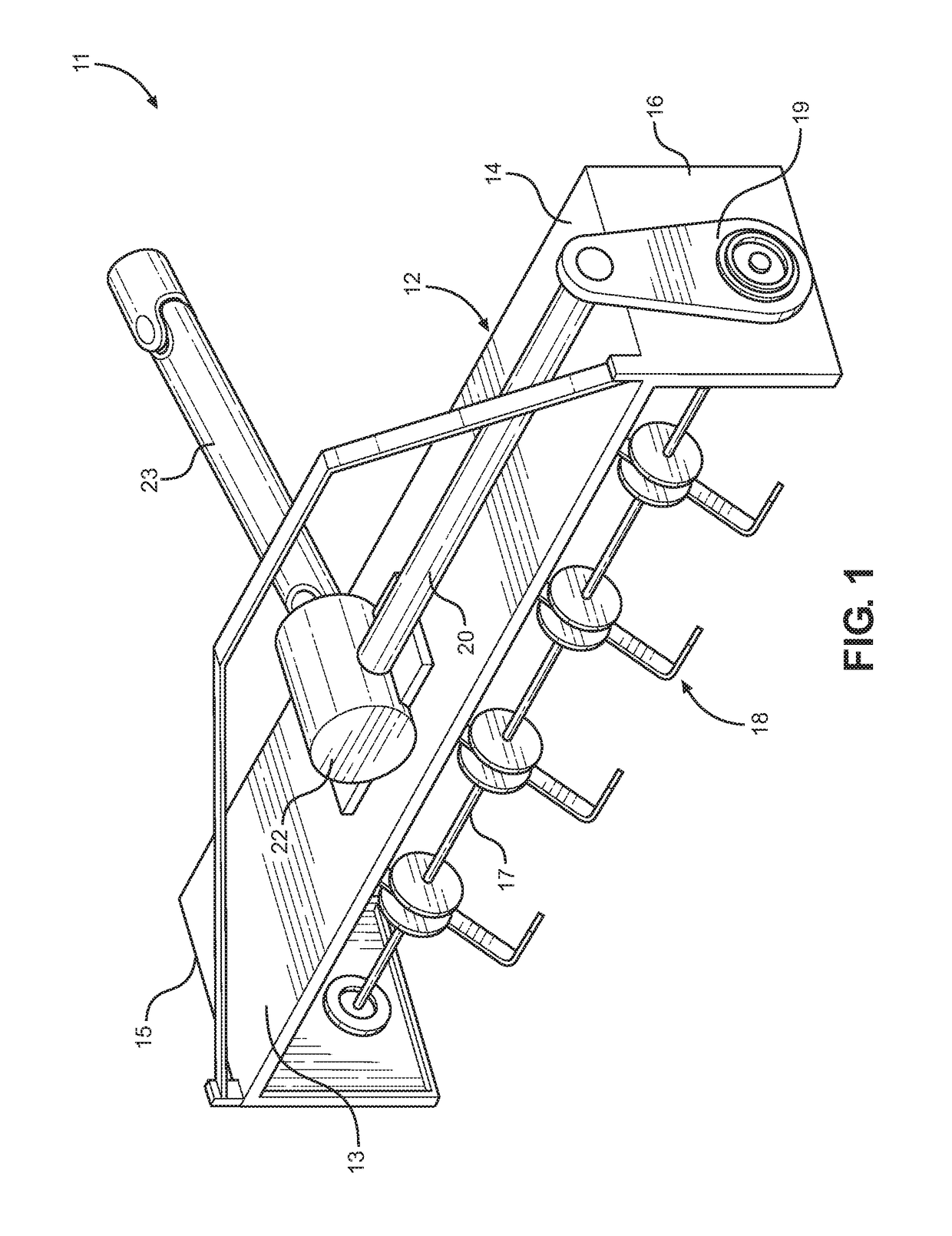
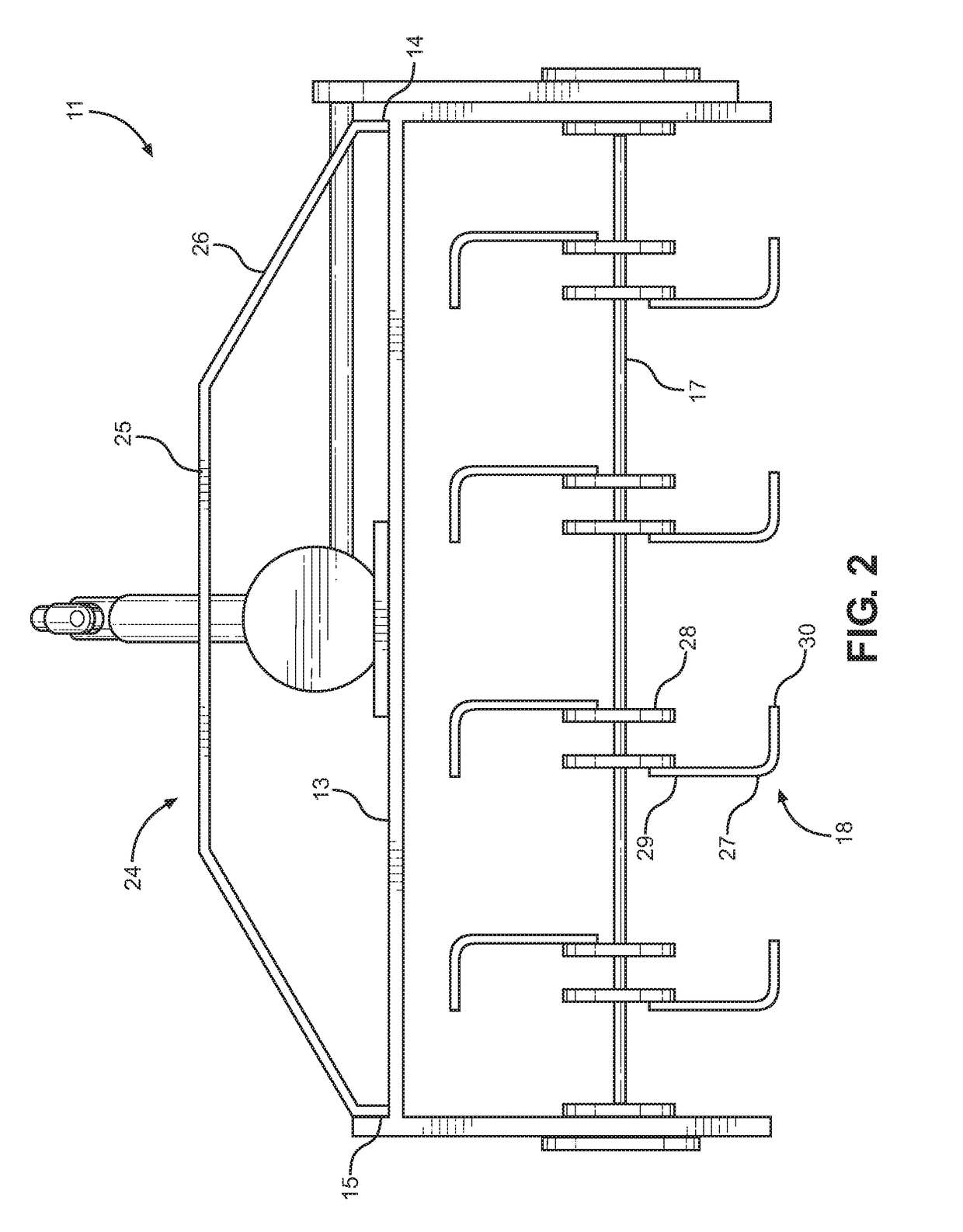
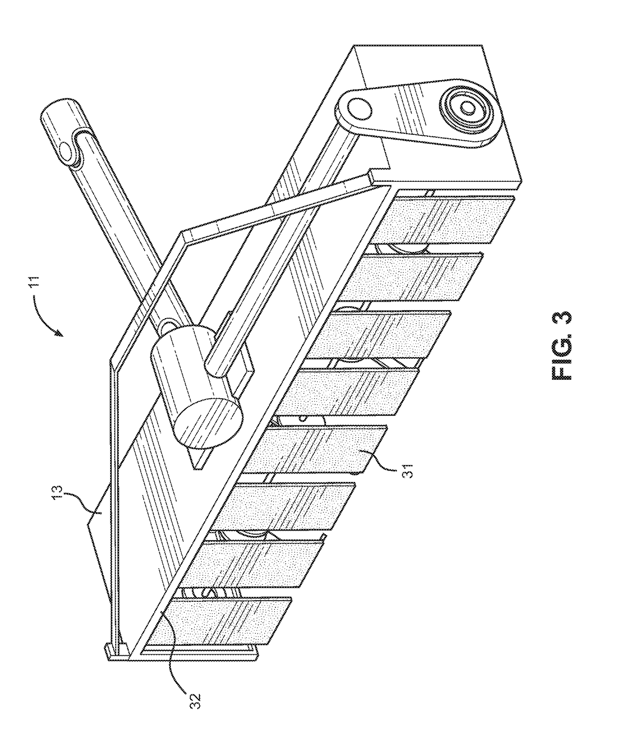
[0017]Reference is made herein to the attached drawings. Like reference numerals are used throughout the drawings to depict like or similar elements of the attachable tilling device. For the purposes of presenting a brief and clear description of the present invention, the preferred embodiment will be discussed as used for creating irrigation channels within the ground for uniformly distributing water to crops. The figures are intended for representative purposes only and should not be considered to be limiting in any respect.

[0018]Referring now to FIG. 1, there is shown a perspective view of an embodiment of the attachable tilling device. The attachable tilling device 11 comprises a housing 12 having a base member 13 including a first end 14 and a second end 15, wherein a pair of opposing side members 16 extend downwardly from the first end 14 and the second end 15 of the base member 13. In the illustrated embodiment, the base member 13 and each of the pair of opposing side members...


PUM


Abstract

An attachable tilling device for a vehicle is provided. The device includes a housing having a base member, wherein a pair of opposing side members extend downwardly from a first end and a second end thereof. A bar member is rotatably affixed between the pair of opposing side members, wherein the bar member rotates about a longitudinal axis. The bar member includes a plurality of tilling blades affixed thereto. A gear system is operably connected to the bar member, wherein the gear system rotates the bar member. A gearbox is disposed on an upper side of the housing, wherein a pair of shaft members are operably connected to the gearbox, wherein a first shaft member connects to the gear system and a second shaft member connects to a motor, such that when the motor is actuated, power is transferred to the gearbox, thereby rotating the plurality of tilling blades.

Description

CROSS REFERENCE TO RELATED APPLICATION[0001]This application claims the benefit of U.S. Provisional Application No. 62 / 517,574 filed on Jun. 9, 2017. The above identified patent application is herein incorporated by reference in its entirety to provide continuity of disclosure.BACKGROUND OF THE INVENTION[0002]The present invention relates to tilling machines used for farming. More specifically, the present invention provides a tilling device that removable secures to vehicle, such as, a tractor.[0003]Many farmers provide irrigation channels in their fields in order to successfully grow crops. Traditionally, farmers use two types of tilling devices to create irrigation channels. The first device uses a broad rotational blade that results in grass and dirt falling into the freshly created irrigation channels, which diverts water to undesired locations. The second tilling device drags cutting blades through the ground, which leads to bunches of grass, dirt and debris falling back into ...

Claims


Application Information

Patent Timeline
IPC IPC(8): A01B33/02A01B33/08
CPCA01B33/021A01B33/082A01B33/087
Inventor QUILLIN, DAVIDQUILLIN, TENA
Owner QUILLIN DAVID
Learn More