Plate heat exchanger

a heat exchanger and plate technology, applied in indirect heat exchangers, laminated elements, lighting and heating apparatus, etc., can solve problems such as fluid leakage, and achieve the effect of preventing positional displacement of gaskets and appropriate sealing of flow channels

Active Publication Date: 2016-01-14
HISAKA WORKS +1
View PDF5 Cites 1 Cited by
  • Summary
  • Abstract
  • Description
  • Claims
  • Application Information

AI Technical Summary

Benefits of technology

[0015]In view of the above circumstances, an object of the present invention is to provide a plate heat exchanger that is capable of preventing positional displacement of a gasket defining a flow channel, and hence maintaining an appropriate sealing performance of a flow channel for circulation of a fluid medium.

Problems solved by technology

When the gaskets are partially deformed in this manner, a relative positional relationship between the gaskets and the heat transfer plates cannot be kept constant, which prevents the sealing performance of the flow channels (the first flow channel and the second flow channel) (the sealing performance between each adjacent heat transfer plates) from being maintained and hence may cause a fluid leakage.

Method used


Image

  • Plate heat exchanger
  • Plate heat exchanger
  • Plate heat exchanger

Examples


Embodiment Construction

[0039]A description is made for a plate heat exchanger according to one embodiment of the present invention with reference to the attached drawings.

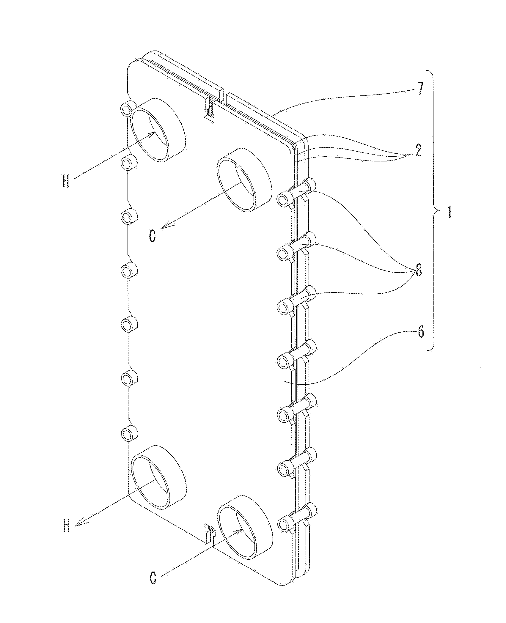
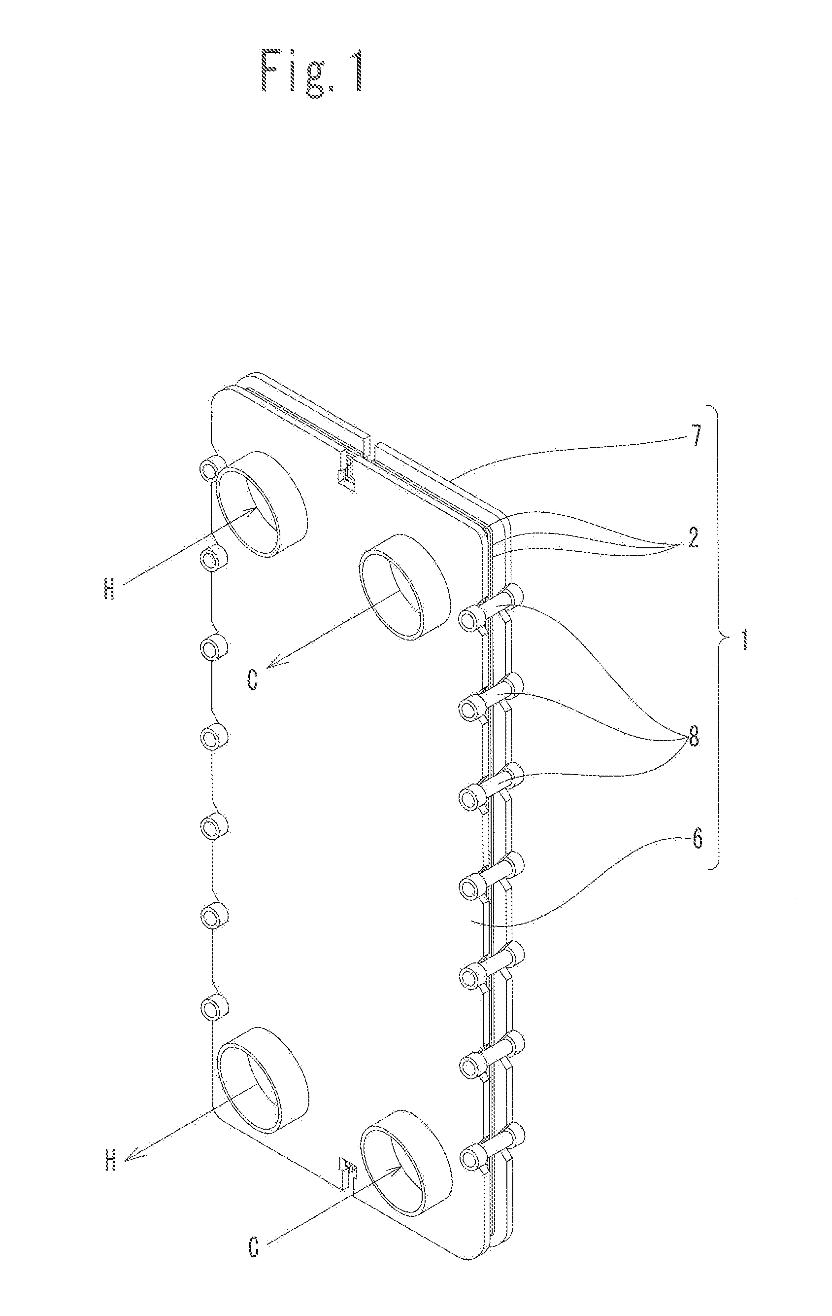
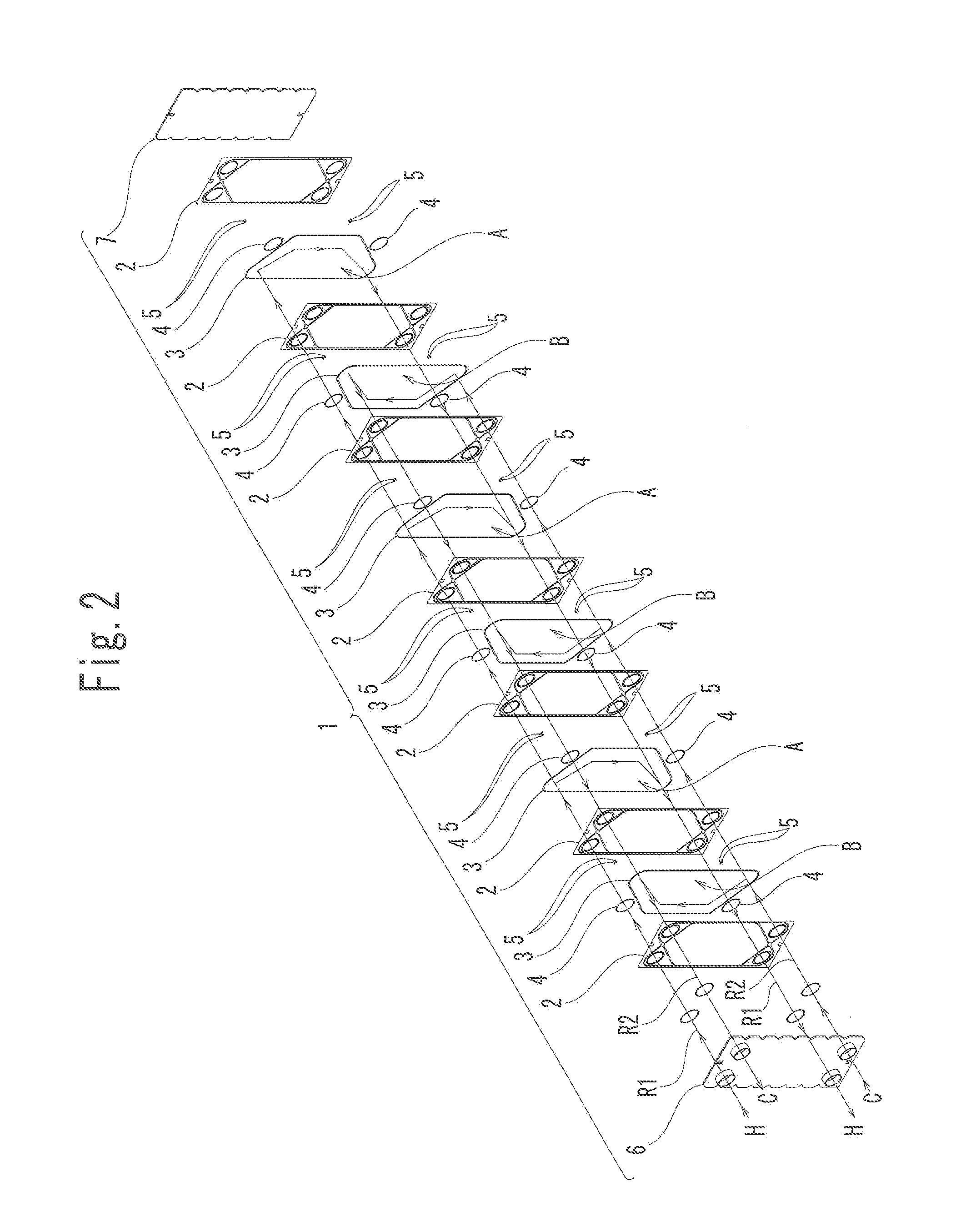
[0040]As shown in FIG. 1, a plate heat exchanger includes a plurality of heat transfer plates 2 stacked to each other. As shown in FIG. 2, a plate heat exchanger 1 according to the present embodiment includes gaskets 3 and 4 interposed between each adjacent heat transfer plates 2, and regulating members 5 formed to be able to at least partially support the gaskets 3 and 4, as well as the plurality of the heat transfer plates 2. Further, as shown in FIG. 1, the plate heat exchanger 1 of the present embodiment includes a pair of frame plates 6 and 7 that sandwich the plurality of the stacked heat transfer plates 2, in which one of the frame plates 6 and 7 has an inflow port and an outflow port, and tie rods 8 for fastening the pair of frame plates 2.

[0041]In the present embodiment, the plurality of the heat transfer plates 2 have the same ...


PUM


Abstract

Provided is a plate heat exchanger that includes a plurality of heat transfer plates stacked to each other, a gasket interposed between each adjacent heat transfer plates, and a regulating member formed to be able to support at least partially the gasket. Each heat transfer plate has a fitting recessed portion formed in recessed manner on the side on which the gasket fitting groove is formed. The fitting recessed portion crosses the recessed strip while extending along the gasket fitting groove. The support part is arranged along the gasket fitting groove when the regulating member is held in fitting engagement with the fitting recessed portion. The support part is arranged along the gasket fitting groove when the regulating member is held in fitting engagement with the fitting recessed portion.

Description

CROSS-REFERENCE TO RELATED APPLICATION[0001]This application claims priority to Japanese Patent Application No. 2013-036919, the disclosure of which is incorporated herein by reference in its entirety.FIELD OF THE INVENTION[0002]The present invention relates to a plate heat exchanger that includes a plurality of heat transfer plates stacked to each other, and a gasket interposed between each adjacent heat transfer plates which defines a flow channel for circulation of a fluid medium.BACKGROUND ART[0003]Hitherto, a plate heat exchanger is proposed as one of a heat exchanger for heat exchange between a first fluid medium and a second fluid medium.[0004]A plate heat exchanger includes a plurality of heat transfer plates. The heat transfer plates each are formed by press molding a metal plate and have a plurality of recessed strips and projected strips formed on each of both front and back sides and at least four openings extending through both the front and back sides.[0005]In the plat...

Claims


Application Information

Patent Timeline
Patent Type & Authority Applications(United States)
IPC IPC(8): F28D9/00
CPCF28D9/0093F28F3/083F28F3/10F28D9/005
Inventor HIWATASHI, ISAMUIWAKI, MANAMATSUMURA, SEIICHIISHIHAMA, KIYOSHI
Owner HISAKA WORKS
Why Eureka
Try Eureka