Attachment structure of camera module and portable terminal device

a technology of camera module and portability, which is applied in the direction of substation equipment, television systems, casings/cabinets/drawer details, etc., can solve the problems of deteriorating the original properties affecting the internal parts of the camera module, and displacement of the optical axis of the lens par

Inactive Publication Date: 2008-06-17
KYOCERA CORP
View PDF15 Cites 46 Cited by
  • Summary
  • Abstract
  • Description
  • Claims
  • Application Information

AI Technical Summary

Benefits of technology

[0009]The first aspect of the present invention is an attachment structure for attaching a camera module to a housing. The camera module having an image capturing element portion mounted on a substrate and a lens portion provided on the image capturing element portion. An elastic member which is elastically deformed in a thickness direction, arranged between the substrate and said housing, and a latching portion provided on the housing. The camera module engages with the latching portion, thereby, the movement of the elastic member in the restoring direction is restricted.

Problems solved by technology

However, when the above-described camera module experiences an impact load, that impact load is readily communicated to the entire structure, causing problems such as disrupting the image formation surface inside the image pickup part, negatively impacting internal parts of the camera module, etc.
Conversely, if an attempt is made to reduce the transmission of impact load by decreasing the strength of the connections between the image pickup part, lens part and substrate, then other problems arise such as displacement of the optical axis of the lens part, and a deterioration in the original properties of the camera module.
In particular, when the camera module is loaded in a portable terminal device, there is a high chance that it will experience an impact load from dropping, etc. of that device.

Method used


Image

  • Attachment structure of camera module and portable terminal device
  • Attachment structure of camera module and portable terminal device
  • Attachment structure of camera module and portable terminal device

Examples


Embodiment Construction

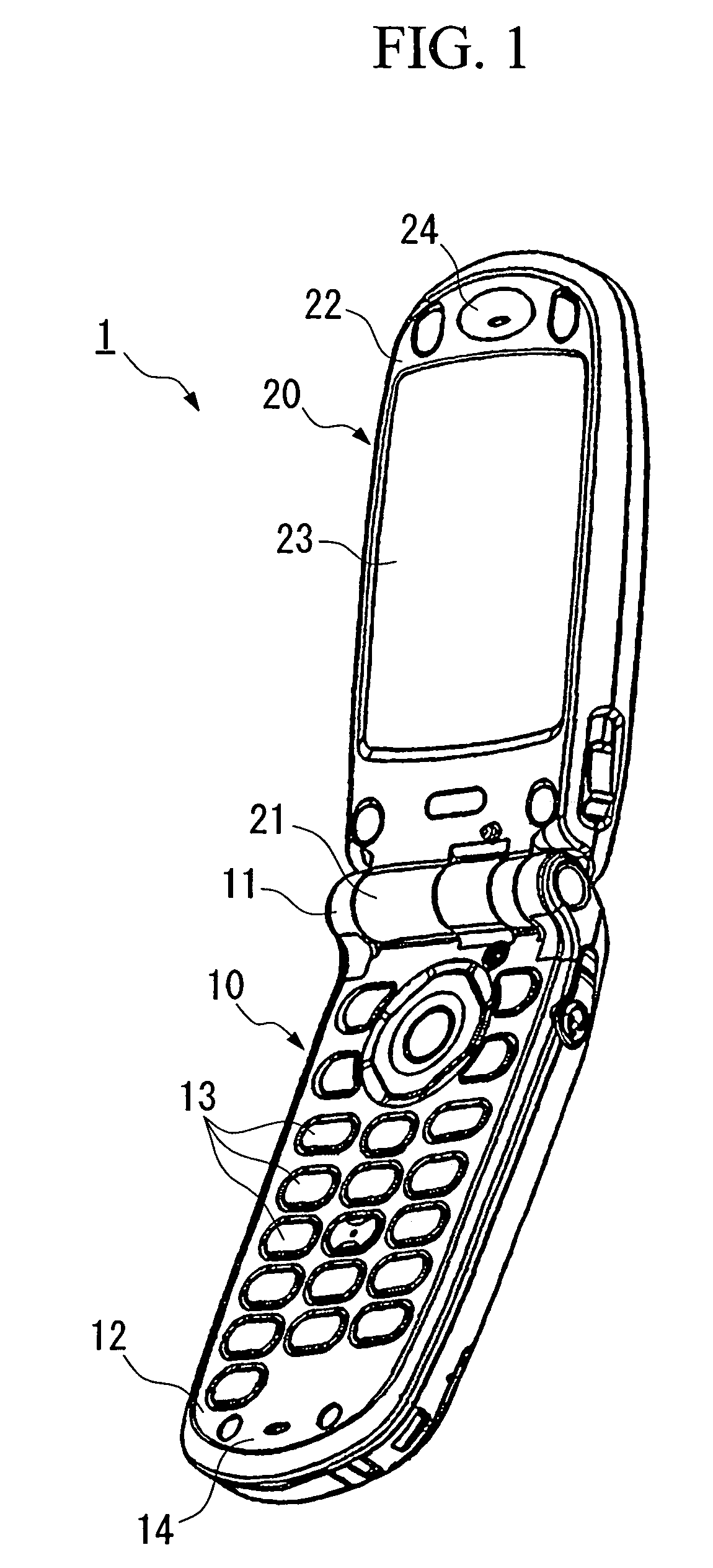
[0026]Preferred embodiments of the present invention will now be explained based on the accompanying Figures. Note that the following explanation employs as an example, a cellular phone in which, a camera module that employs the camera module attachment structure of the present invention has been mounted.

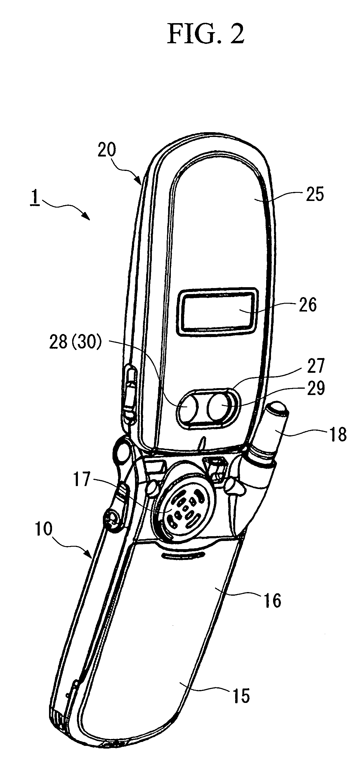
[0027]Cellular phone 1 (portable terminal device) shown in FIG. 1 is designed as a foldable cellular phone having a first housing 10 and a second housing 20 that are formed in the shape of a flat, roughly rectangular parallelepiped. These housings stacking on top of one another when cellular phone 1 is folded. As shown in FIG. 1 the longitudinal direction of first housing 10 and second housing 20 is defined as the vertical direction. A first hinge 11 is provided at the top side of first housing 10, and a second hinge 21 is provided at the bottom side of second housing 20. By connecting these hinges 11 and 21 via a hinge shaft not shown in FIG. 1, first housing 10 and second housing ...


PUM


Abstract

An attachment structure of a camera module for attaching to a housing a camera module having an image capturing element portion mounted on a substrate and a lens portion provided on said image capturing element portion. The attachment structure includes an elastic member which is elastically deformed in a thickness direction, arranged between said substrate and said housing, and a latching portion provided on said housing. The camera module engages with said latching portion, and movement of said elastic member in the restoring direction is restricted.

Description

CROSS-REFERENCE TO RELATED APPLICATION[0001]This application claims priority from and incorporates herein by reference the commonly-assigned Japanese Patent Application Number 2002-347072, filed on Nov. 29, 2002 and entitled “Attachment Structure of Camera Module and Portable Terminal Device.”BACKGROUND OF THE INVENTION[0002]1. Field of the Invention[0003]The present invention relates to an attachment structure for attaching a camera module in a housing of a portable terminal device. Examples of such portable terminal devices include cellular phones, PHS (personal handy phones), PDAs (Personal Data Assistants), and notebook computers.[0004]2. Description of Prior Art[0005]The use of portable terminal devices such a cellular phones that are provided with a small camera module has grown increasingly common in recent years.[0006]Of camera modules of this type, there is a design available that is provided with an image pickup part employing CCD (charge-coupled device) and a lens part fo...

Claims


Application Information

Patent Timeline
Patent Type & Authority Patents(United States)
IPC IPC(8): H04N5/225H04M1/00H04M1/02H05K7/12H04M1/21H05K5/02H05K11/00
CPCH04M1/0214H04M1/0264
Inventor YAMAZAKI, MASATO
Owner KYOCERA CORP
Why Eureka
Try Eureka