UV curing system and process

a curing system and ultraviolet technology, applied in the field of ultraviolet curing, can solve the problems of uneven curing of products, time-consuming and inefficient prior art techniques, etc., and achieve the effects of improving ultraviolet curing, reducing time consumption, and reducing time consumption

Inactive Publication Date: 2010-09-30
CON TROL CURE
View PDF41 Cites 47 Cited by
  • Summary
  • Abstract
  • Description
  • Claims
  • Application Information

AI Technical Summary

Benefits of technology

[0013]An improved ultraviolet (UV) curing method and apparatus are provided which quickly, efficiently and effectively cures UV curable products, articl...

Problems solved by technology

Many of the prior art techniques are time-consuming a...

Method used


Image

  • UV curing system and process
  • UV curing system and process
  • UV curing system and process

Examples


Embodiment Construction

[0060]A detailed description of the preferred embodiments and best modes for practicing the invention are described herein.

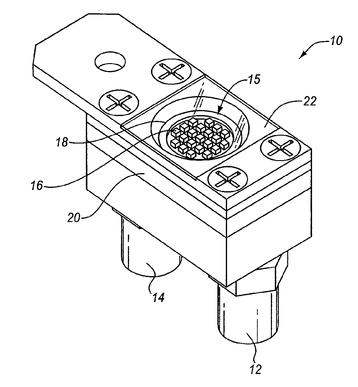
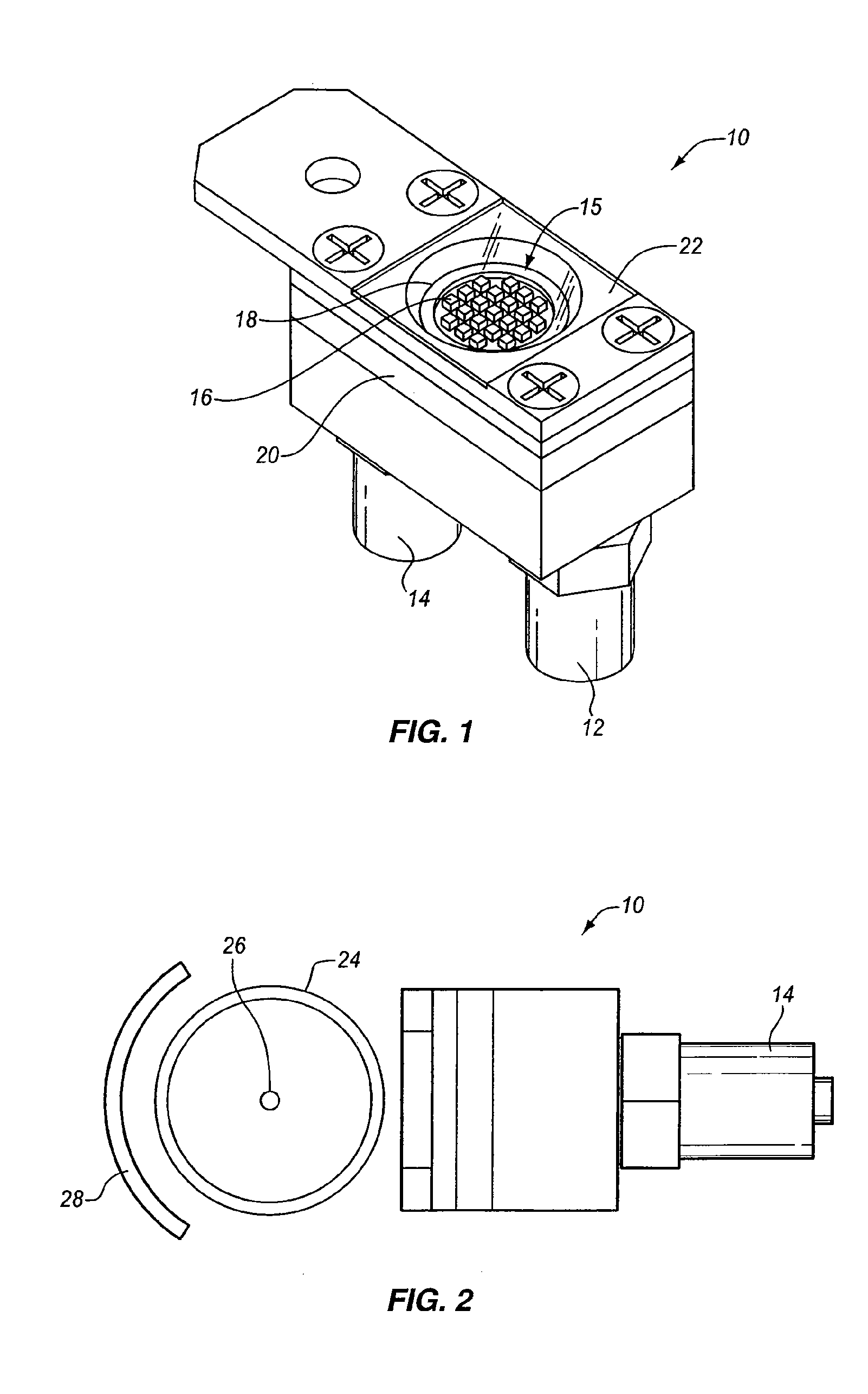
[0061]UV-LED's (ultraviolet light emitting diodes) are being used more and more for curing UV curable inks, coatings and adhesives on a variety of different products. Typically such LED's are 0.346 mm2. Also they typically are powered with three to five volts and a power drain of 30 milliwatts.

[0062]The power output of LED's is being increased so that higher intensity UV light can be emitted by the LED's. As a result, new arrays of UV LED's require more driving power, emit more light and generate more heat. Furthermore, new super high power UV-LED modules are considerably more expensive than the earlier modules with smaller, less inexpensive lower power UV-LED chips that emit low intensity UV light. With small, inexpensive lower power UV-LED chips it is practical to use hundreds or even thousands, e.g., 10,000, chips to create an array of low power UV-LED's to i...


PUM


Abstract

A rotatably indexable and stackable apparatus and method for UV curing an elongated member or at least one UV-curable ink, coating or adhesive applied thereon is further disclosed, comprising at least one UV-LED mounted on one side of the elongated member, and an elliptically-shaped reflector positioned on the other side of the elongated member opposite the at least one UV-LED.

Description

CROSS REFERENCE[0001]This application is a continuation-in-part of U.S. application Ser. No. 12 / 050,616 filed Mar. 18, 2008 for “Rotary UV Curing Method And Apparatus,” which is a divisional of U.S. application Ser. No. 10 / 753,837 filed Jan. 7, 2004 for “Rotary UV Curing Method And Apparatus,” now abandoned, which is a continuation-in-part of U.S. application Ser. No. 10 / 386,980 filed Mar. 12, 2003 for “Multiple Wavelength UV Curing,” now abandoned, which is a continuation-in-part of U.S. application Ser. No. 10 / 339,264 filed Jan. 9, 2003 for “Light Emitting Apparatus and Method For Curing Inks, Coatings And Adhesives,” now issued as U.S. Pat. No. 7,175,712, all of which are incorporated herein by reference in their entirety.BACKGROUND OF THE INVENTION[0002]1. Field of the Invention[0003]The present invention relates to a method for ultraviolet (UV) curing of inks, coatings and adhesives having UV photo initiators therein which, when exposed to UV light, convert monomers in the inks...

Claims


Application Information

Patent Timeline
IPC IPC(8): F26B3/34
CPCB41F23/0409B41J11/002E04F11/1836F26B21/14F26B3/28F26B3/283F26B13/10E04F11/1863B41J11/00214
Inventor SIEGEL, STEPHEN B.
Owner CON TROL CURE
Why Eureka
Try Eureka