Tray table apparatus

a technology for stowable tray tables and apparatuses, which is applied to rigid tables, bed tables, trays, etc., can solve the problems of too many degrees of freedom too easily bumped tables, and easy use of stowable tray tables, etc., and achieves the effect of convenient adjustment and convenient us

Active Publication Date: 2016-01-21
SCHULMAN CARL H
View PDF20 Cites 9 Cited by
  • Summary
  • Abstract
  • Description
  • Claims
  • Application Information

AI Technical Summary

Benefits of technology

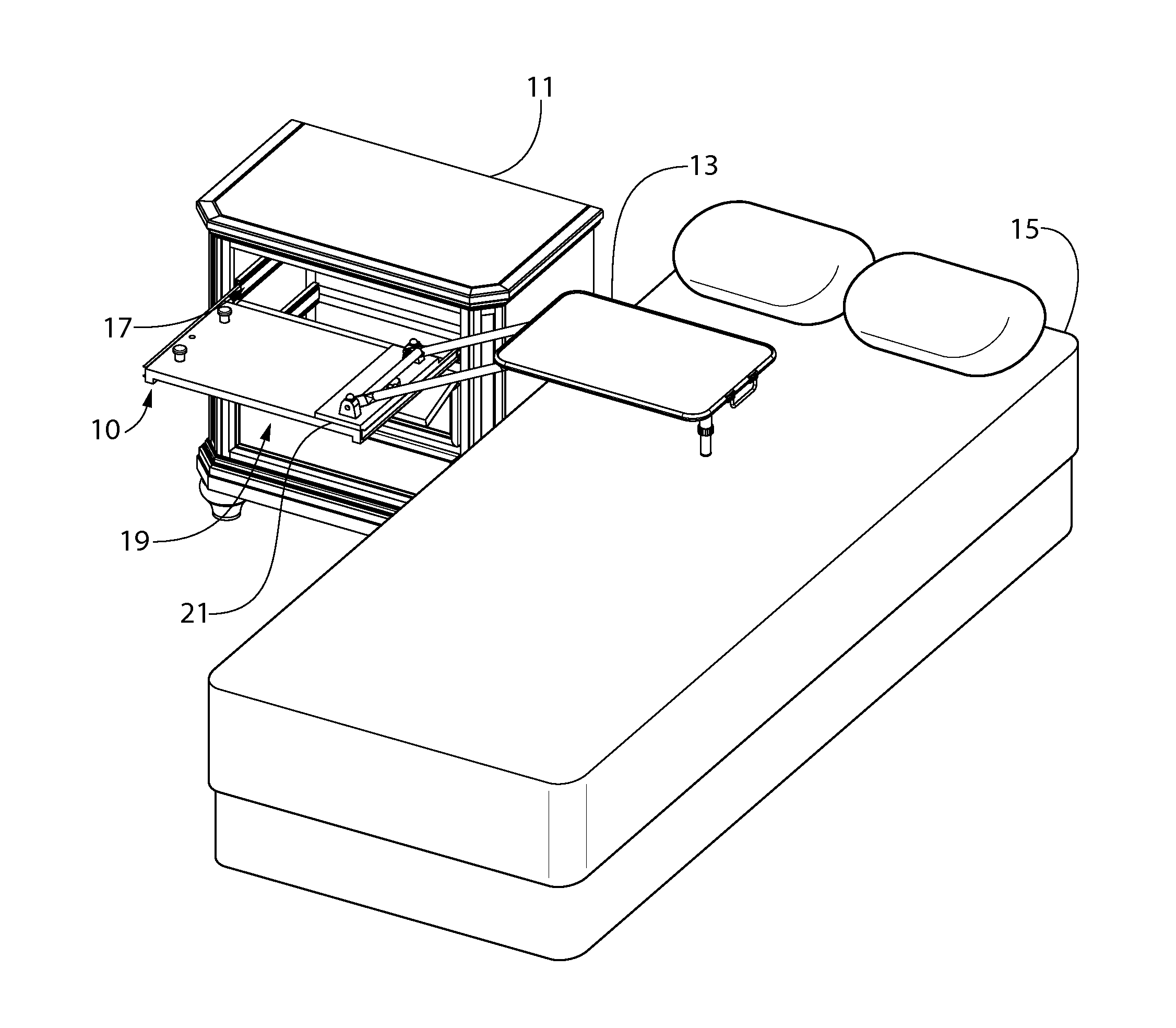
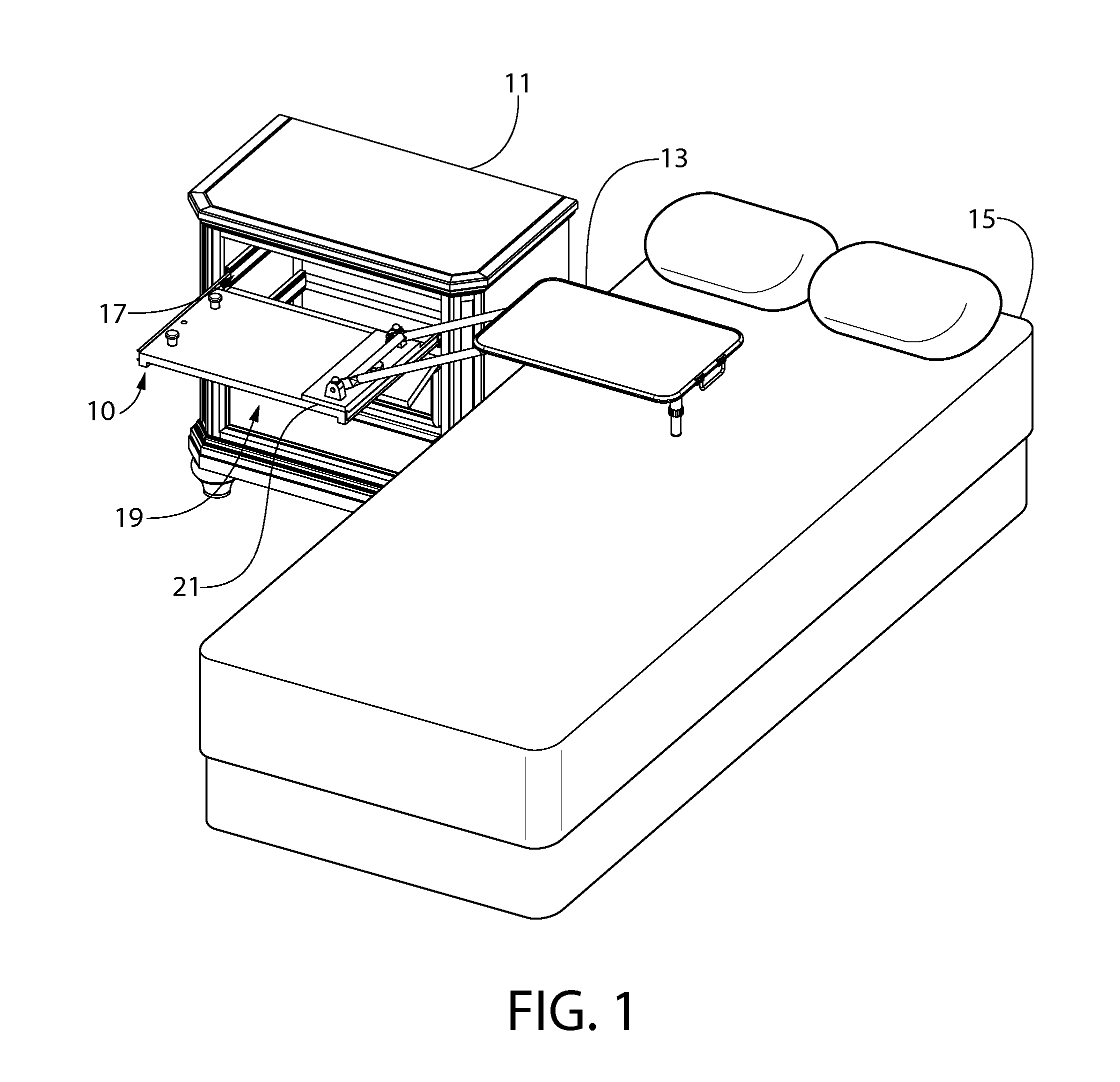
[0005]The present invention is directed toward a tray table apparatus which includes a tray table which is movable between a stowed position to a deployed position. When not in use, the tray table may be stowed out of the way in the stowed position. The stowable tray table is made to be particularly easy to use by a person lying in a bed. When in use, the tray table provides adjustment mechanisms by which a person may easily adjust at least two degrees of freedom: the height of the tray table above another surface, such as a bed, and the lateral position of the tray table between, such as between the head and foot of a bed.

Problems solved by technology

Such stowable tray tables are known in the art, however they often are attached to limitations that turn their use into a frustrating convenience.
For example, some stowable tray tables have too many degrees of freedom, such as is seen in the tray table disclosed in U.S. Pat. No. 1,220,578, as all the degrees of freedom make the tray table too easily bumped out of the position in which it is set.
Others have more limited degrees of freedom, but some of those degrees of freedom are not easy to use for a person who is lying in the bed and needs to adjust the position of the bed tray, such as the tray table disclosed in U.S. Pat. No. 3,054,122.

Method used


Image

  • Tray table apparatus
  • Tray table apparatus
  • Tray table apparatus

Examples


Embodiment Construction

[0027]The description of illustrative embodiments according to principles of the present invention is intended to be read in connection with the accompanying drawings, which are to be considered part of the entire written description. In the description of embodiments of the invention disclosed herein, any reference to direction or orientation is merely intended for convenience of description and is not intended in any way to limit the scope of the present invention. Relative terms such as “lower,”“upper,”“horizontal,”“vertical,”“above,”“below,”“up,”“down,”“left,”“right,”“top” and “bottom” as well as derivatives thereof (e.g., “horizontally,”“downwardly,”“upwardly,” etc.) should be construed to refer to the orientation as then described or as shown in the drawing under discussion. These relative terms are for convenience of description only and do not require that the apparatus be constructed or operated in a particular orientation unless explicitly indicated as such. Terms such as ...


PUM


Abstract

A tray table apparatus including a tray table and a tray table support assembly coupled to the tray table. The tray table and the tray table support assembly are configured to transition between a stowed position and a deployed position. The tray table support assembly includes: a support shelf; a support arm having a first end pivotably coupled to the support shelf so as to be pivotable about a first pivot axis and a second end, the tray table pivotably coupled to the second end of the support arm so as to be pivotable about a tray table pivot axis; and an adjustable pivot stop positioned to limit pivot movement of the support arm about the first pivot axis in the deployed position, such that a selected adjustment position of the adjustable pivot stop determines an angle of inclination formed between the support arm and the support shelf.

Description

CROSS REFERENCE TO RELATED APPLICATIONS[0001]The present application claims the benefit of U.S. Provisional Patent Application Ser. No. 62 / 026,062, filed Jul. 18, 2014, the disclosure of which is incorporated herein by reference in its entirety.FIELD OF THE INVENTION[0002]The field of the present invention relates to tray tables, such as tray tables which may extend out over a bed for use as an in-bed table and may retract when not being used.BACKGROUND OF THE INVENTION[0003]Tray tables for use in the bed are common, and for people who choose or need to eat, read, or work in bed, having a bedside tray table that extends out over the bed when needed and stows out of the way is an indispensable convenience. Such stowable tray tables are known in the art, however they often are attached to limitations that turn their use into a frustrating convenience. For example, some stowable tray tables have too many degrees of freedom, such as is seen in the tray table disclosed in U.S. Pat. No. 1...

Claims


Application Information

Patent Timeline
Patent Type & Authority Applications(United States)
IPC IPC(8): A47B23/02A47B3/08A47B23/00A47B83/04
CPCA47B23/02A47B83/045A47B23/001A47B3/08
Inventor SCHULMAN, CARL, H.
Owner SCHULMAN CARL H
Why Eureka
Try Eureka