Portable cervical traction device

a cervical traction device and portability technology, applied in the field of cervical traction devices, can solve the problems of not typically providing support for the patient's shoulders, conventional cervical traction devices do not include a self-adjusting halter assembly, etc., and achieve the effect of maximum therapeutic benefi

Inactive Publication Date: 2016-01-21
HOLLYWOG
View PDF9 Cites 9 Cited by
  • Summary
  • Abstract
  • Description
  • Claims
  • Application Information

AI Technical Summary

Benefits of technology

[0006]Among the advantages of a preferred embodiment of the invention is that provides a cervical traction device having multiple interchangeable self-storing head support cushions for use in positioning the patient's head and neck in any of several angular positions with respect to the patient's shoulders. Another advantage of a preferred embodiment of the invention is that it includes a support component for the patient's shoulders that assists in properly positioning the patient to receive traction therapy. Still another advantage of a preferred embodiment of the invention is that it includes a halter assembly which cooperates with the shoulder support component and the selected head support cushion for properly positioning the cervical spine of a patient to obtain a maximum therapeutic benefit.
[0007]Additional objects and advantages of this invention will become apparent from an examination of the drawings and the ensuing description.
[0008]The use of the terms “a”, “an”, “the” and similar terms in the context of describing the invention are to be construed to cover both the singular and the plural, unless otherwise indicated herein or clearly contradicted by context. The terms “comprising”, “having”, “including” and “containing” are to be construed as open-ended terms (i.e., meaning “including, but not limited to,”) unless otherwise noted. The terms “substantially”, “generally” and other words of degree are relative modifiers intended to indicate permissible variation from the characteristic so modified. The use of such terms in describing a physical or functional characteristic of the invention is not intended to limit such characteristic to the absolute value which the term modifies, but rather to provide an approximation of the value of such physical or functional characteristic. All methods described herein can be performed in any suitable order unless otherwise specified herein or clearly indicated by context.
[0009]The use of any and all examples or exemplary language (e.g., “such as” and “preferably”) herein is intended merely to better illuminate the invention and the preferred embodiments thereof, and not to place a limitation on the scope of the invention. Nothing in the specification should be construed as indicating any element as essential to the practice of the invention unless so stated with specificity. Several terms are specifically defined herein. These terms are to be given their broadest possible construction consistent with such definitions, as follows:
[0010]The terms “above”, “upper” and similar terms, when used with respect to a traction device or a component of a traction device, refer to a relative location or direction away from the surface on which the device is placed during operation.
[0011]The terms “below”, “lower” and similar terms, when used with respect to a traction device or a component of a traction device, refer to a relative location or direction towards the surface on which the device is placed during operation.

Problems solved by technology

Such traction devices do not typically provide support for the patient's shoulders in such a way as to help to position the patient properly with respect to the traction apparatus.
In addition, conventional cervical traction devices do not include a self-adjusting halter assembly for properly positioning the head and neck of a patient with respect to the patient's shoulders to obtain a maximum therapeutic benefit.

Method used


Image

  • Portable cervical traction device
  • Portable cervical traction device
  • Portable cervical traction device

Examples


first embodiment

[0053]FIG. 13A is an illustration of a head halter that is a part of the preferred embodiment of the invention.

[0054]FIG. 13B is an illustration of the head halter shown in FIG. 13A, showing how it is attached to a patient and to the cervical traction device shown in FIGS. 1-6.

second embodiment

[0055]FIG. 14A is an illustration of a head halter that is a part of the preferred embodiment of the invention.

[0056]FIG. 14B is an illustration of the head halter shown in FIG. 14A, showing how it is attached to a patient and to the cervical traction device shown in FIGS. 1-6.

DESCRIPTION OF THE PREFERRED EMBODIMENT OF THE INVENTION

embodiment 20

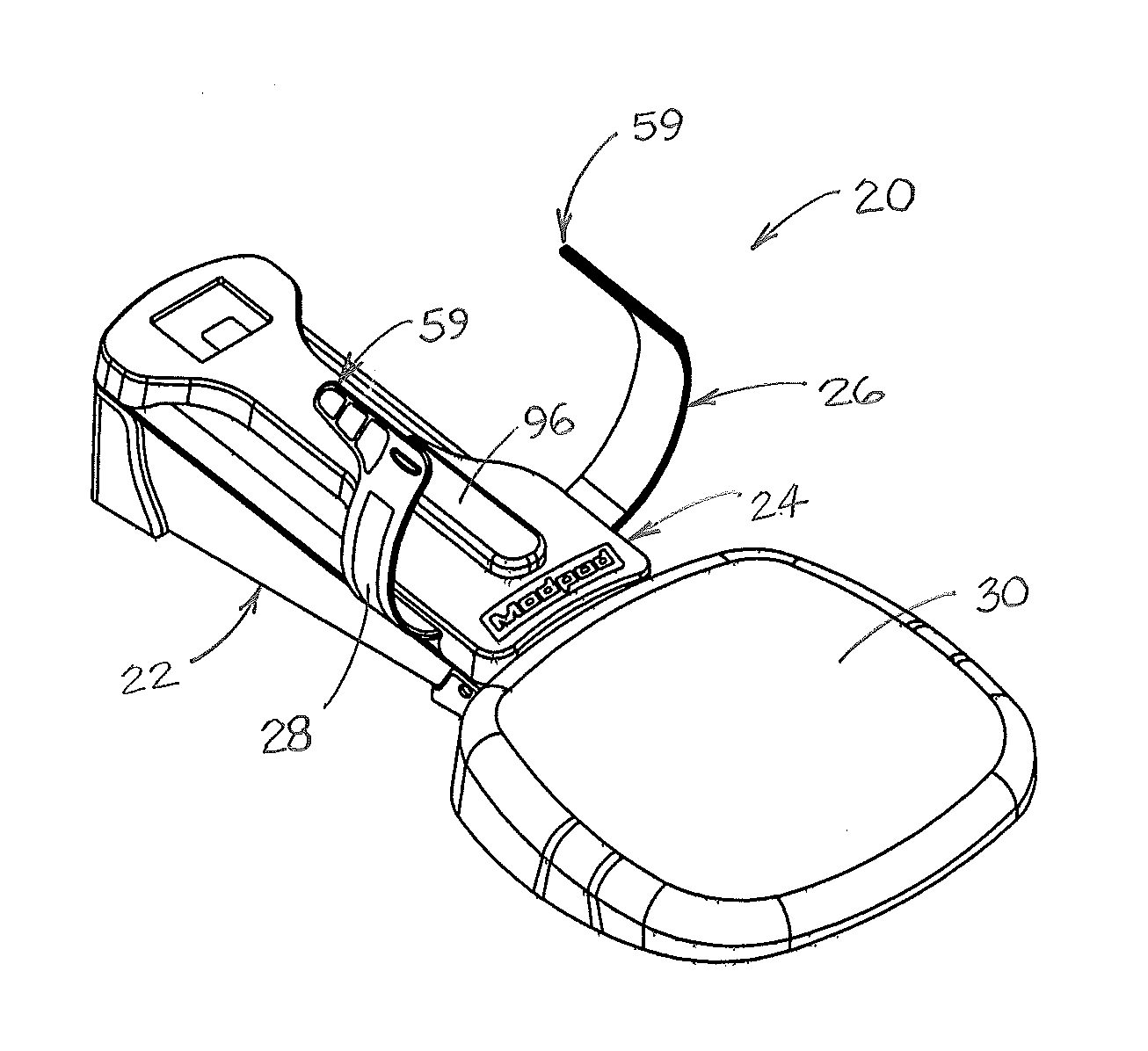
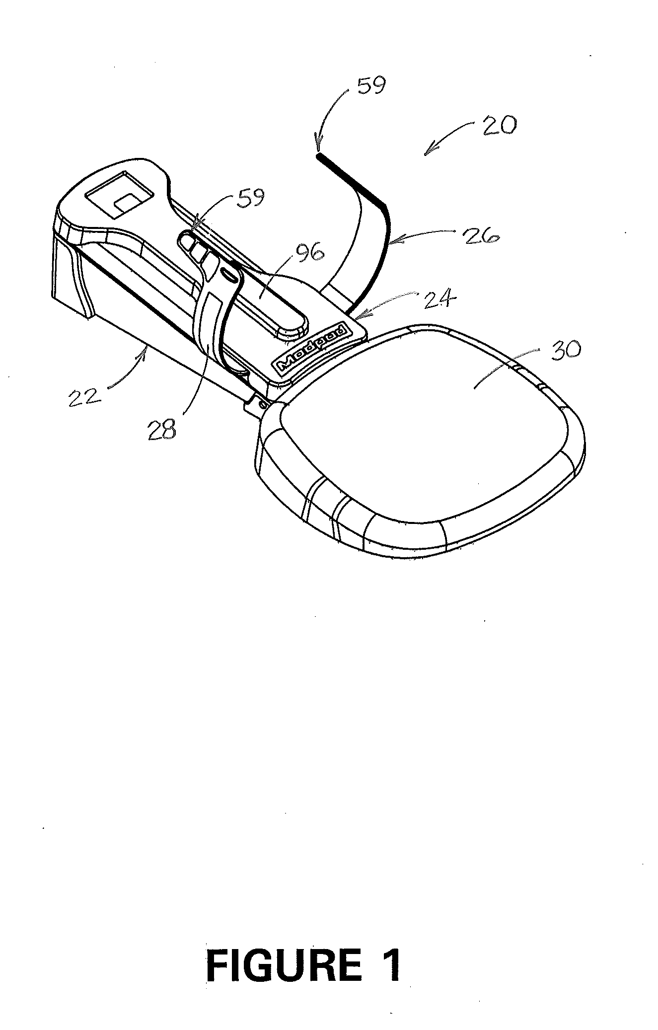
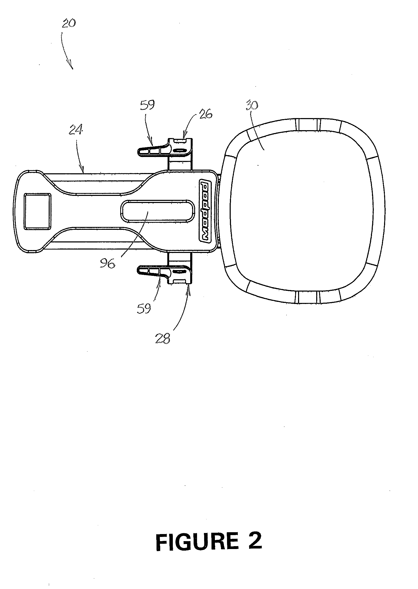
[0057]A preferred embodiment 20 of a cervical traction device is illustrated in the drawings. As shown therein, cervical traction device 20 includes base assembly 22, sled assembly 24, left and right halter supports 26 and 28 respectively, and shoulder support cushion 30.

[0058]As shown in FIG. 6, base assembly 22 includes base frame 32, front closure 34, and sled frame 36. Two low-friction sled runners 38 are attached to the sled frame to facilitate movement of sled assembly 24 on the sled frame. Preferably, sled runners 38 are comprised of a blend of polycarbonate and glass fibers. Enclosed within base assembly 22 is linear actuator 40 (best shown in FIG. 7). Rear end 42 of linear actuator 40 is attached to load cell assembly 44 and to rear support 46 of the base assembly. Front end 48 of linear actuator 40 is attached to sled assembly 24. The load cell assembly is operatively attached to the linear actuator and to controller and interactive display assembly 49 located on controlle...


PUM


Abstract

A cervical traction device includes a base assembly having a sled frame and a sled assembly that is adapted to move along the sled frame. The device includes a plurality of unique head support cushions. The sled assembly includes a recess that is adapted to removably receive each of the plurality of head support cushions. The device also includes a shoulder support cushion and a halter assembly having a head halter that is adapted to be removably attached to the head of the patient. A linear actuator is attached between the base assembly and the sled assembly and adapted to move the sled assembly along the sled frame.

Description

CROSS-REFERENCE TO RELATED APPLICATION[0001]This application claims the benefit of U.S. Provisional Patent Application No. 62 / 025,860, which was filed on Jul. 17, 2014.FIELD OF THE INVENTION[0002]This invention relates generally to cervical traction devices. More specifically, the invention relates to a portable cervical traction device that may be placed on any suitable surface for use in applying traction forces to the cervical musculature and spine.BACKGROUND AND DESCRIPTION OF THE PRIOR ART[0003]Traction devices are commonly used to relieve pressure on inflamed or pinched nerves. Cervical traction devices generally operate by applying a traction force to the head and / or neck of a patient, and lumbar traction devices generally operate by applying a traction force to the lumbar spine. Such devices can relieve pain in the neck and lower back by stretching the cervical and / or lumbar musculature and spine. Generally, traction devices operate by applying a series of traction or pullin...

Claims


Application Information

Patent Timeline
Patent Type & Authority Applications(United States)
IPC IPC(8): A61F5/37A61F5/055
CPCA61F5/3707A61F5/055A61H1/0296A61H2201/0157A61H2201/123A61H2201/1607A61H2201/1664A61H2201/50A61H2201/5061A61H2203/0456A61H2201/0192A61H2201/5043A61H2201/5058
Inventor THOMAS, CHARLES M.HAGY, D. KEITHDUNCAN, THU-HA THIMARSHALL, JOHN S.HILL, GUY T.HUGHES, HERBERT ALLENHUGHES, CHRISTOPHER SHAWNHAWKINS, ANITA
Owner HOLLYWOG
Why Eureka
Try Eureka