Portable cervical traction device with suspension head halter
- Summary
- Abstract
- Description
- Claims
- Application Information
AI Technical Summary
Benefits of technology
Problems solved by technology
Method used
Image
Examples
Embodiment Construction
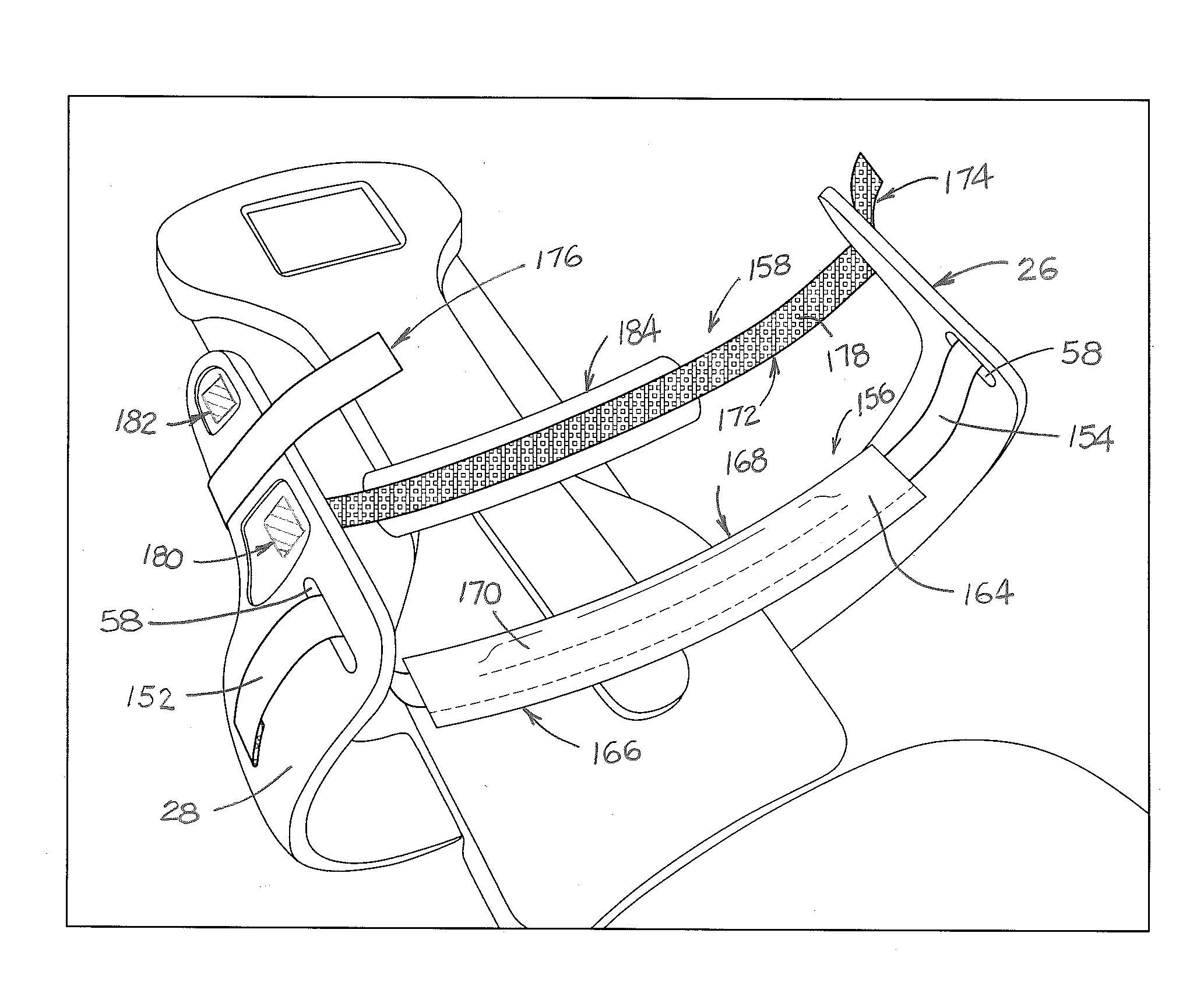
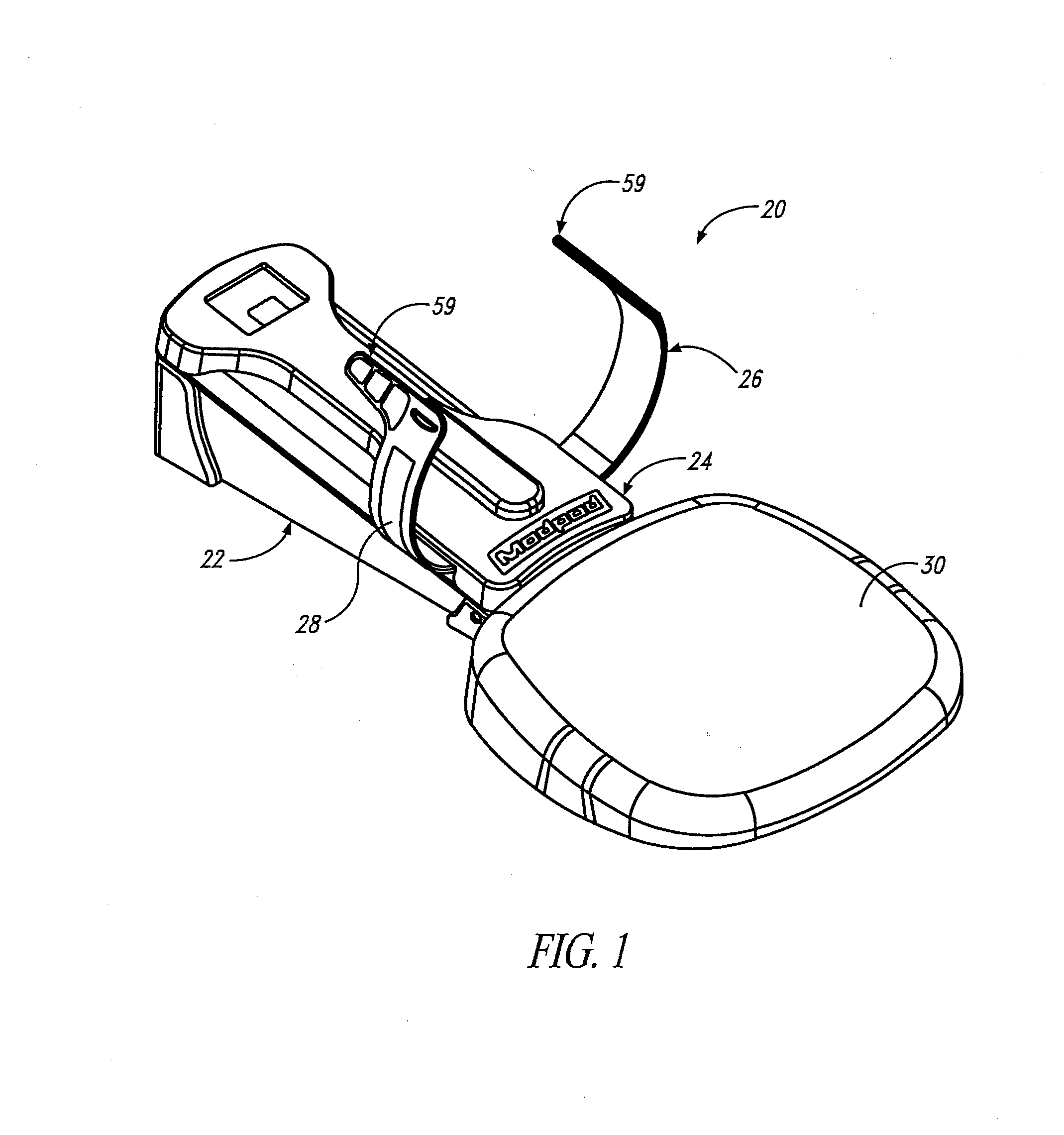
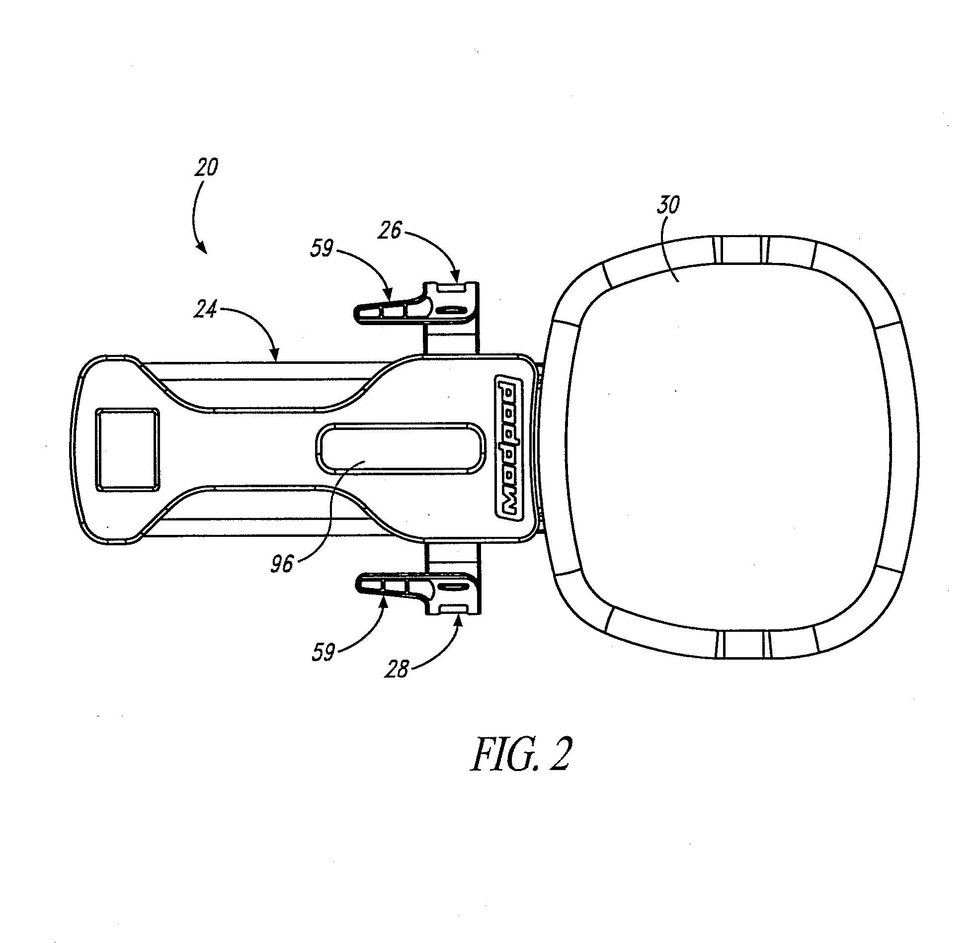
[0062]A preferred embodiment 20 of a cervical traction device is illustrated in the drawings. As shown therein, cervical traction device 20 includes base assembly 22, sled assembly 24, left and right halter supports 26 and 28 respectively, and shoulder support cushion 30.
[0063]As shown in FIG. 6, base assembly 22 includes base frame 32, front closure 34, and sled frame 36. Two low-friction sled runners 38 are attached to the sled frame to facilitate movement of sled assembly 24 on the sled frame. Preferably, sled runners 38 are comprised of a blend of polycarbonate and glass fibers. Enclosed within base assembly 22 is linear actuator 40 (best shown in FIG. 7). Rear end 42 of linear actuator 40 is attached to load cell assembly 44 and to rear support 46 of the base assembly. Front end 48 of linear actuator 40 is attached to sled assembly 24. The load cell assembly is operatively attached to the linear actuator and to controller and interactive display assembly 49 located on controlle...
PUM
 Abstract
Description
Claims
Application Information
 - R&D
- Intellectual Property
- Life Sciences
- Materials
- Tech Scout
- Unparalleled Data Quality
- Higher Quality Content
- 60% Fewer Hallucinations
Browse by: Latest US Patents, China's latest patents, Technical Efficacy Thesaurus, Application Domain, Technology Topic, Popular Technical Reports.
© 2025 PatSnap. All rights reserved.Legal|Privacy policy|Modern Slavery Act Transparency Statement|Sitemap|About US| Contact US: help@patsnap.com


