A catheter assembly

a catheter and assembly technology, applied in the field of catheter assembly, can solve the problems of not being suitable for indwelling catheters, not being suitable for catheters, and difficult for users to reduce dexterity

Active Publication Date: 2016-01-28
COLOPLAST AS
View PDF7 Cites 6 Cited by
  • Summary
  • Abstract
  • Description
  • Claims
  • Application Information

AI Technical Summary

Problems solved by technology

Hydrophilic coated catheters, where the coating absorbs a considerable amount of liquid for a low friction surface (swelling degree >100%), will not be suitable for indwelling catheters, because the hydrophilic surface coating would stick to the mucosa inside the urethra if left inside the body for a longer period, due to the hydrophilic coating transforming from being highly lubricious whe

Method used


Image

  • A catheter assembly
  • A catheter assembly
  • A catheter assembly

Examples


Embodiment Construction

[0086]It should be understood that the detailed description and specific examples, while indicating embodiments of the invention, are given by way of illustration only, since various changes and modifications within the spirit and scope of the invention will become apparent to those skilled in the art from this detailed description.

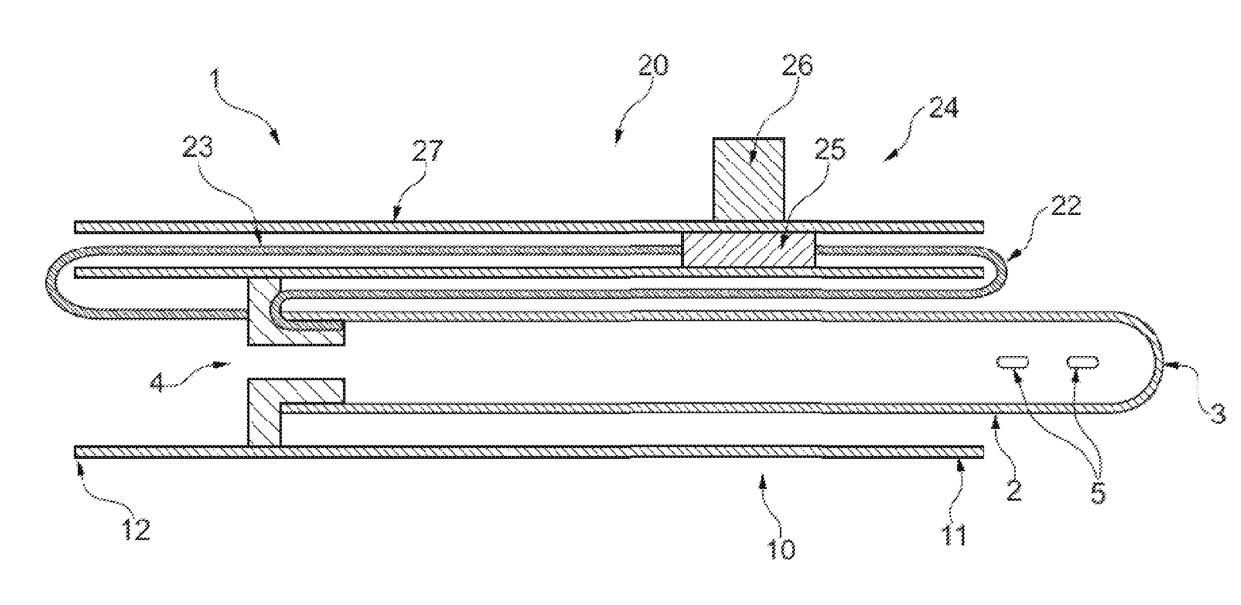
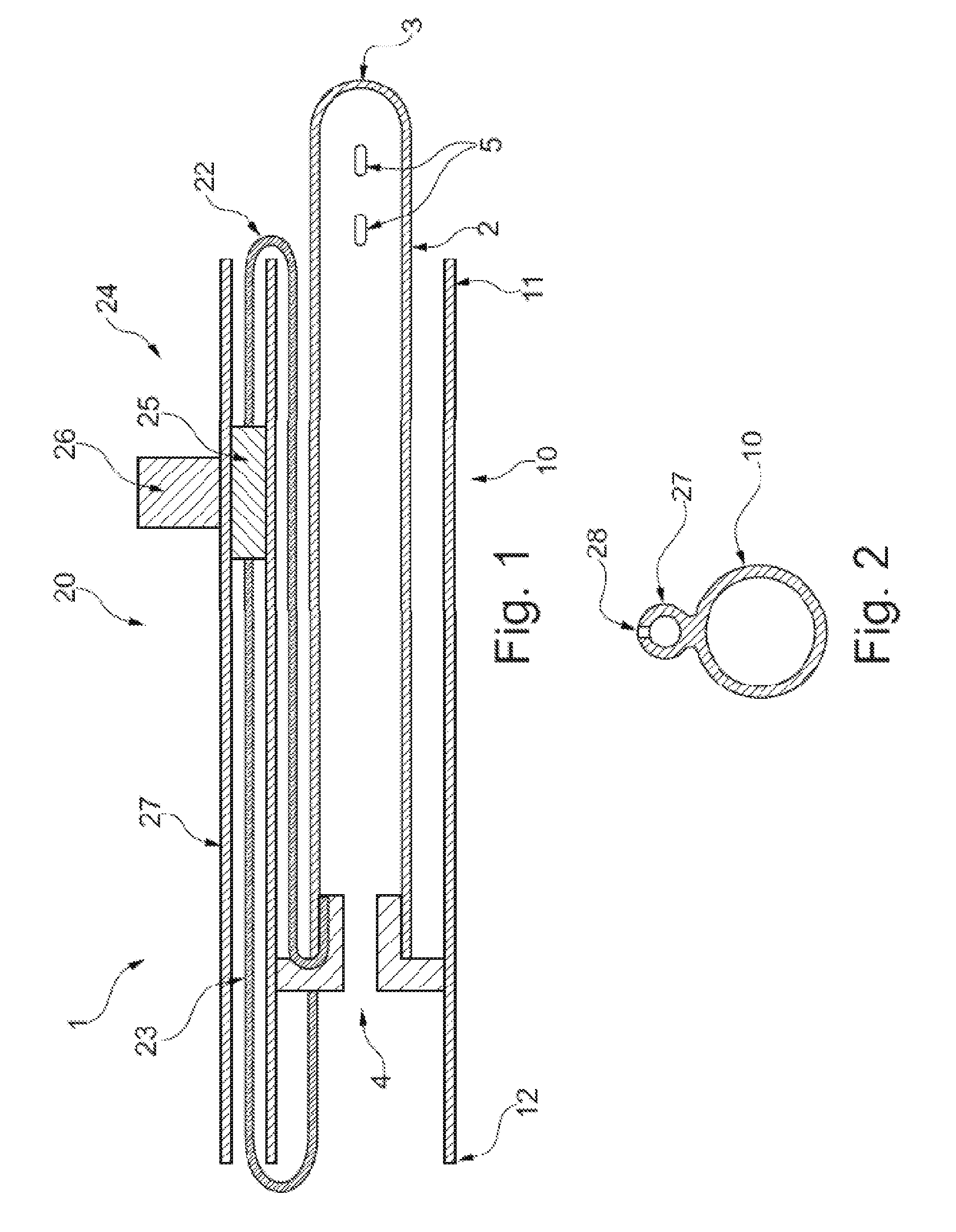
[0087]FIG. 1 illustrates a cross-sectional view of a catheter assembly 1 according to a first series of embodiments the invention. The catheter assembly 1 comprises a catheter 2 with a proximal insertion end 3 and a distal end 4. The distal end 4 is wider than the tubular part of the catheter. The catheter is further provided with eyelets 5 for leading urine from the bladder into the inner lumen of the catheter. In the figure, the catheter 2 is contained in a first tube 10, see e.g. FIG. 5 showing the embodiment in a perspective view. The widened distal end 4 provides a slight friction against the inner surface of the first tube 10 so as to prevent the ca...


PUM

PropertyMeasurementUnit
Forceaaaaaaaaaa

Abstract

The invention provides a catheter (1) which is movable between an un-expanded and an expanded configuration by use of an advancing mechanism (20). The advancing mechanism facilitates safe and non-contaminated use of the catheter.

Description

INTRODUCTION[0001]The invention relates to a catheter assembly, particularly for intermittent catheterisation.BACKGROUND[0002]Urinary catheter assemblies for draining the bladder are increasingly used for intermittent as well as indwelling or permanent catheterisation. Typically, urinary catheters are used by patients suffering from urinary incontinence or by disabled individuals like paraplegics or tetraplegics, who may have no control permitting voluntary urination and for whom catheterisation may be the way of urinating.[0003]Urinary catheters are divided into two major groups of catheters, indwelling catheters and intermittent catheters. Indwelling catheters are typically inserted into the urethra and the bladder by medical personal (i.e. a trained professional, typically a nurse or physician) and has means for retaining the catheter inside the bladder for up to two weeks or more.[0004]Indwelling catheters are soft and flexible since they have to remain in the urethra for weeks....

Claims


Application Information

Patent Timeline
IPC IPC(8): A61M25/01A61M25/00
CPCA61M25/0111A61M25/002A61M25/0045A61M25/0113A61M2025/0175A61M2210/1096A61M2025/0046A61M25/0017A61M25/0105A61M2025/0056A61M2202/0496A61M2205/0222A61M2205/0238A61M2210/1085A61M2202/0014A61M2210/005
Inventor SCHERTIGER, LARS OLAVWINDEBALLE, LARS STENDEVAD
Owner COLOPLAST AS
Why Eureka
Try Eureka