
Devices and Methods for Accessing the Vasculature of a Patient

Active Publication Date: 2016-01-28
BIOCARDIA
View PDF2 Cites 13 Cited by
  • Summary
  • Abstract
  • Description
  • Claims
  • Application Information

AI Technical Summary

Benefits of technology

The patent is about a new device that makes it easier to access areas of the blood vessels that are difficult to reach. The device is a guide catheter that can be steered to different vascular positions. It has a thin wall and is designed to be easily inserted through percutaneous routes. The guide catheter has a deflection tube that allows it to make very tight turns, making it possible to access regions of the blood vessels that were previously inaccessible. The guide catheter can be used in a variety of interventional procedures.

Problems solved by technology

The variety of achievable shapes is also limited because the guide must be inserted into the body in the straight configuration, so that the guide can be advanced to the location of interest without dragging or scraping along the vessel walls.
This flexibility detracts from the guide's ability to support interventional devices that are inserted through it.
Also, the curvature of a pre-shaped guide must be limited, or it will not straighten out when the obturator is inside of it.
These blockages can lead to heart attacks and death.
In many of the procedures, the fixed shape of the guide is not quite right for the patient anatomy and the surgeon must wrestle to get the guide into position, or discard the guide and try another shape.
This consumes significant time in the catheterization lab which has costs today that run roughly $20 per minute.
Although fixed guide catheters are relatively cheap medical devices today, the inability to access a target site in the body quickly due to anatomical variation or the propagation of disease can quickly cost hundreds of dollars.
Extensive time in a fluoroscopy suite also exposes the physician and the patient unnecessarily high doses of radiation.
This patent does not enable a tight radius bending deflectable guide catheter that can track over a guidewire to locations of interest in the vascular tree in patients.
However, the bending point of this catheter is proximal of the end of the catheter, which results in a large sweep distance during bending, which is not desirable.
Also, this catheter has a stiffer braided portion distal to the bending section, which decreases the trackability of the catheter.
Also, this patent does not enable the construction of the shaft with a large central lumen or detail the cross sectional construction.

Method used


Image

  • Devices and Methods for Accessing the Vasculature of a Patient
  • Devices and Methods for Accessing the Vasculature of a Patient
  • Devices and Methods for Accessing the Vasculature of a Patient

Examples


Embodiment Construction

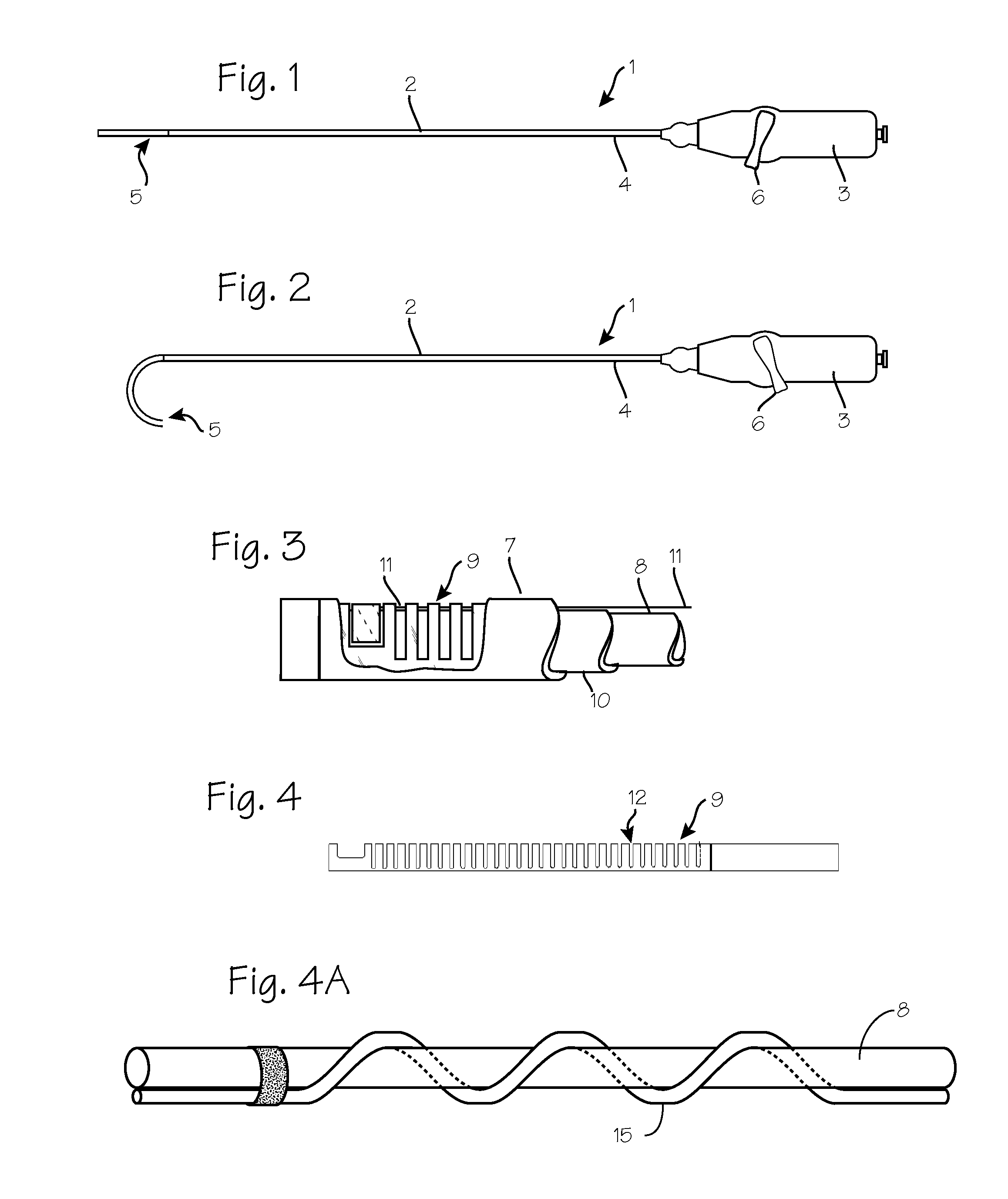
[0036]FIG. 1 illustrates the deflectable guide catheter with the tip in its straight configuration. The guide catheter 1 comprises a steerable guide catheter tube 2 with a catheter handle 3 mounted on the proximal end 4 of the guide catheter tube. The distal end of the guide catheter tube includes a deflectable segment 5 which is operated by a pullwire via manipulation of a steering lever 6 on the proximal handle. As illustrated in FIG. 2, the deflectable segment is bent in an arc as the steering lever turned by the operator.

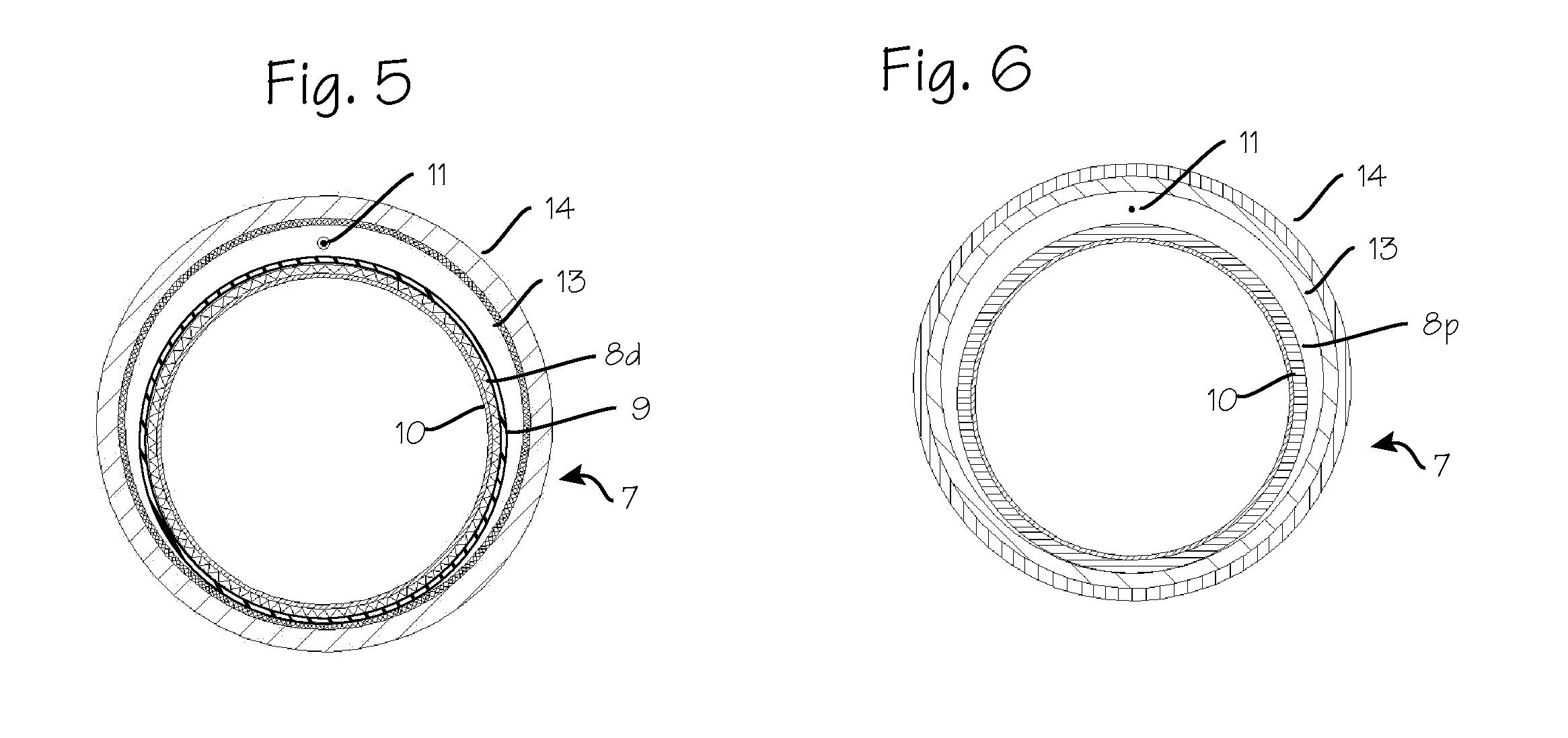
[0037]FIG. 3 is a cutaway view of the distal end of the deflectable guide in FIG. 1. As shown in FIG. 3, the deflectable segment of the guide catheter tube 2 is comprised of an outer catheter shaft 7 and a catheter inner tube 8, with a deflection tube 9 sandwiched between the two. A PTFE liner 10 is disposed within the catheter inner tube 8. That portion of the catheter inner tube 8 which resides inside the deflection tube (item 8d) comprises a coil covered with...


PUM

PropertyMeasurementUnit
Tensionaaaaaaaaaa

Abstract

A steerable guide sheath system adapted for delivery into a patient's vasculature. The pull wire which is used to tension the deflectable portion of the sheath is wrapped or twisted around the axis of the sheath.

Description

[0001]This application is a continuation-in-part of U.S. application Ser. No. 14 / 798,181, filed Jul. 13, 2015, which is a continuation of U.S. application Ser. No. 13 / 965,807, filed Aug. 13, 2013, now U.S. Pat. No. 9,078,994, which is a division of U.S. application Ser. No. 12 / 177,338, filed Jul. 22, 2008, now U.S. Pat. No. 8,939,960, which is a continuation of U.S. application Ser. No. 11 / 016,448 filed Dec. 17, 2004 now U.S. Pat. No. 7,402,151, each of which is hereby incorporated by reference, in its entirety. This application is also a continuation-in-part of U.S. application Ser. No. 13 / 288,918, filed Nov. 3, 2011, which claims priority to Provisional Patent Application 61 / 409,929 filed Nov. 3, 2010, each of which is hereby incorporated by reference, in its entirety.FIELD OF THE INVENTIONS[0002]The inventions described below relate the field of steerable guide catheters and sheaths.BACKGROUND OF THE INVENTIONS[0003]Guide catheters are used to gain access to the desired target lo...

Claims


Application Information

Patent Timeline
IPC IPC(8): A61M25/01
CPCA61M25/0147A61F2/2427A61M25/0045A61M25/0136A61M25/0138A61M25/0141A61M25/0152A61M2025/0687A61M25/0052A61M25/0051A61B2017/00309
Inventor ROSENMAN, DANIEL C.KAYSER, DANIELALTMAN, PETER A.
Owner BIOCARDIA
Learn More