Display unevenness correction apparatus, display apparatus, method for correcting display unevenness, an method for manufacturing the display apparatus

a technology for display panels and unevenness, which is applied in the field of display apparatuses, display apparatuses, and methods for correcting display unevenness, can solve the problems of affecting the uniformity of display panels, affecting the diffusion of backlight light, etc., and achieves the effect of suppressing unevenness and reducing luminan

Inactive Publication Date: 2016-01-28
PANASONIC INTELLECTUAL PROPERTY MANAGEMENT CO LTD
View PDF13 Cites 21 Cited by
  • Summary
  • Abstract
  • Description
  • Claims
  • Application Information

AI Technical Summary

Benefits of technology

[0009]According to the display unevenness correction apparatus, the display apparatus, a method for correcting display unevenness, and the method for manufacturing the display apparatus of the present disclosure, a reduction in luminance which occurs in correcting the luminance unevenness of the display panel can be suppressed.

Problems solved by technology

However, the luminance of the display panel may be un-uniform due to luminance unevenness attributed to cell performance or the like, luminance unevenness attributed to backlights, etc.
The luminance unevenness attributed to backlights includes luminance unevenness which is attributed to a difference in performance of individual backlights, and luminance unevenness due to a fact that spaces between the diffuser and the backlights are narrowed because of a decreased thickness of the LCD display and this impedes sufficient diffusion of light from the backlights.

Method used

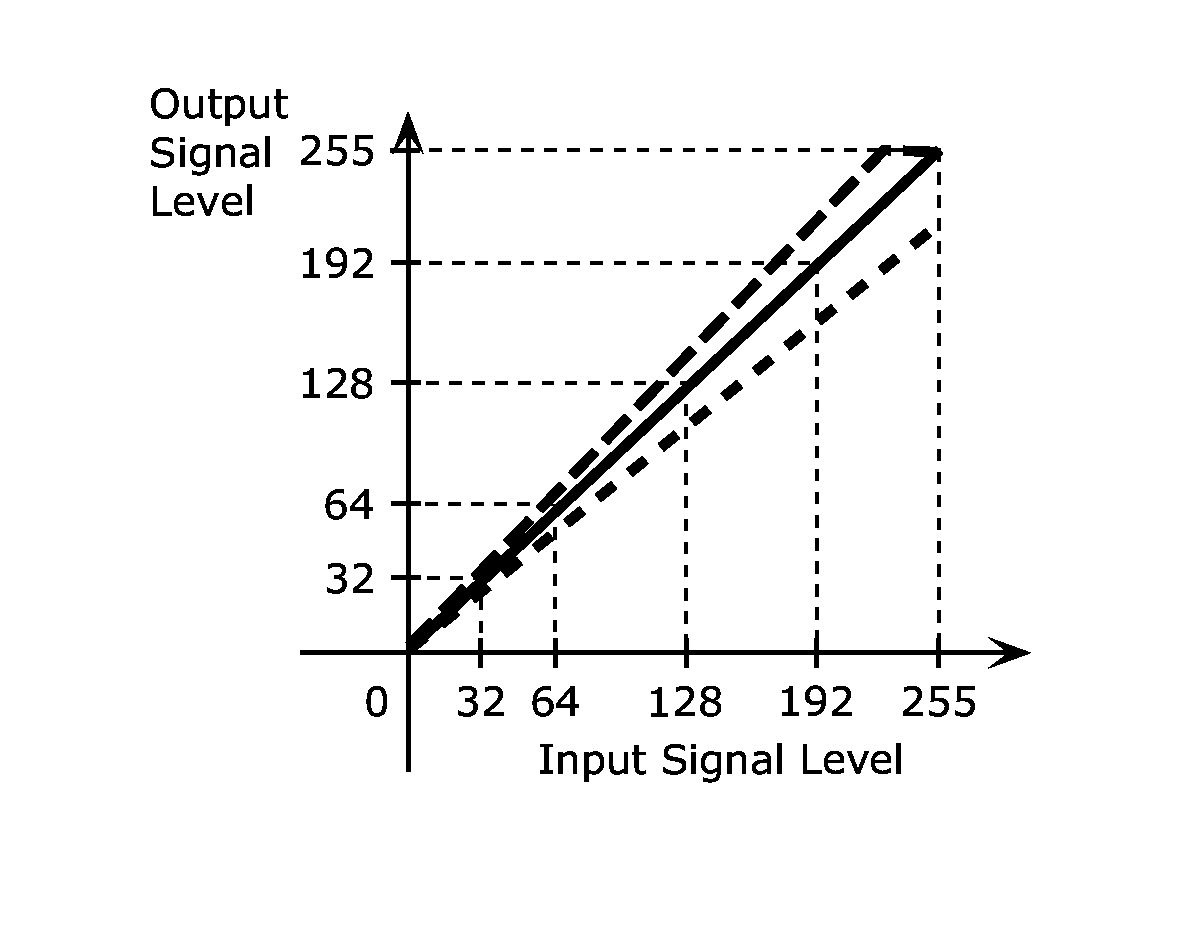
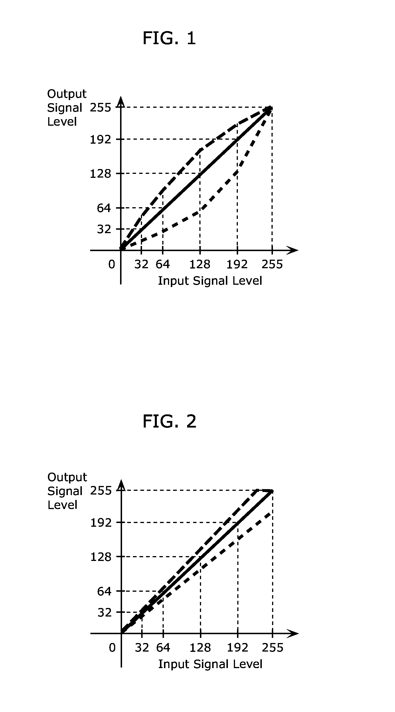
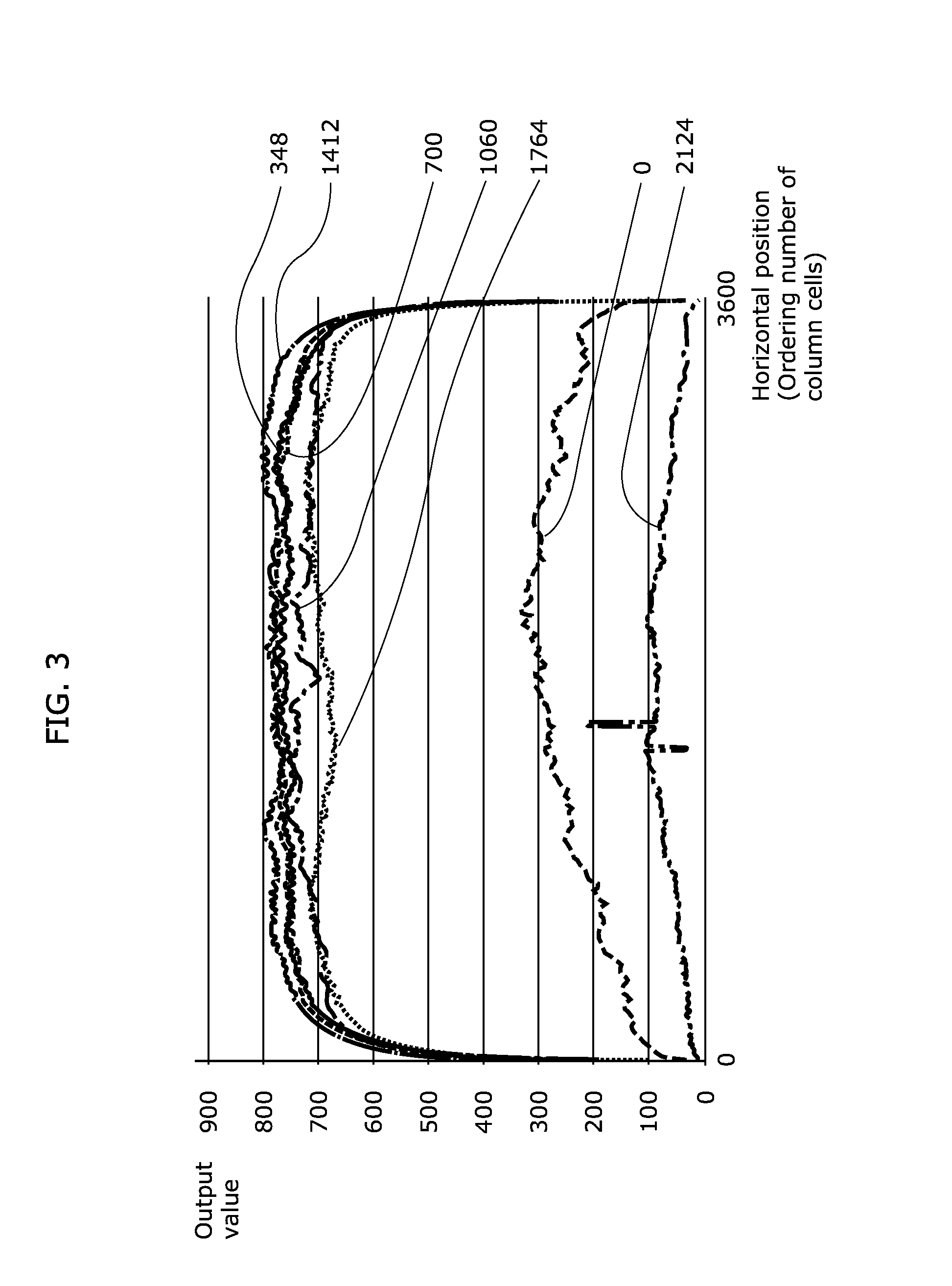

Image

  • Display unevenness correction apparatus, display apparatus, method for correcting display unevenness, an method for manufacturing the display apparatus
  • Display unevenness correction apparatus, display apparatus, method for correcting display unevenness, an method for manufacturing the display apparatus
  • Display unevenness correction apparatus, display apparatus, method for correcting display unevenness, an method for manufacturing the display apparatus

Examples


embodiment 1

[0033]A display unevenness correction apparatus, a display apparatus, a method for correcting display unevenness, and a method for manufacturing the display apparatus according to an embodiment 1 will be described, with reference to FIGS. 4 through 12.

[0034]To suppress a significant reduction in luminance, the display unevenness correction apparatus according to the present embodiment calculates a block luminance for each block, rather than setting the target luminances to the lowest luminance across the display panel. The block luminance is a reference of the luminances in the block. The block luminance is used to calculate the target luminance for each display pixel.

[1-1. Configuration]

[0035]FIG. 4 is a perspective view showing an example of the display unevenness correction apparatus and the display apparatus according to the present embodiment. FIG. 5 is a block diagram of an example of configuration of the display unevenness correction apparatus and the display apparatus accord...

embodiment 2

[0115]A display unevenness correction apparatus, a display apparatus, a method for correcting display unevenness, and a method for manufacturing the display apparatus according to an embodiment 2 will be described, with reference to FIGS. 13 and 14.

[0116]In the present embodiment, the correction gains calculated in the embodiment 1 are further corrected to correct changes in appearance of luminance unevenness depending on a viewing angle.

[0117]Here, a change in angle at which an LCD panel 42 is seen (hereinafter variously, referred to as a “viewing angle”) changes a path of light output from backlights 45, thereby chancing an amount of light blocked by liquid crystal. Thus, the change in viewing angle may end up shifting the appearance of the luminance unevenness attributed to the backlights 45 vertically or horizontally, or changing the intensity.

[0118]Hence, in the present embodiment, as described above, the correction gains calculated in the embodiment 1 are further corrected to ...


PUM


Abstract

A display unevenness correction apparatus for use in the manufacture of an LCD display including an LCD panel having display pixels arranged in rows and columns, the apparatus including: a luminance meter which measures a luminance of the LCD panel while the LCD panel is being illuminated to obtain a luminance; a block luminance calculation unit which segments the luminance map into first blocks and calculate, for each of the first blocks, a block luminance of the first block using luminances included in the first block, the block luminance representing the luminances included in the first block; an interpolation unit which calculates a target luminance for each of the display pixels, using a corresponding one of the block luminances; and a correction gain calculation unit which calculates a correction coefficient for each display pixel using the target luminance.

Description

TECHNICAL FIELD [0001]The present disclosure relates to a display unevenness correction apparatus, a display apparatus, a method for correcting display unevenness, and a method for manufacturing the display apparatus.BACKGROUND ART [0002]For example, a liquid crystal (LCD) display by way of example of display includes an LCD panel in which a plurality of display pixels (hereinafter variously, referred to as “cells”) are arranged in a matrix, backlights, such as light emitting diodes (LEDs), disposed on the back of the LCD panel, and a diffuser for diffusing light output from the individual LEDs. It is desirable from a standpoint of video quality that the LCD display adjusts luminances of the plurality of cells to be uniform if uniform tonal signals are input.[0003]However, the luminance of the display panel may be un-uniform due to luminance unevenness attributed to cell performance or the like, luminance unevenness attributed to backlights, etc. The luminance unevenness attributed ...

Claims


Application Information

Patent Timeline
Patent Type & Authority Applications(United States)
IPC IPC(8): G09G3/00G01J1/44G09G3/36
CPCG09G3/006G01J1/44G09G2320/0693G01J2001/4247G09G2320/0233G09G3/3611G09G3/36G09G2320/0285G09G2360/147G09G2360/16
Inventor TERAI, HARUKOFUNAMOTO, KAZUHIRO
Owner PANASONIC INTELLECTUAL PROPERTY MANAGEMENT CO LTD
Why Eureka
Try Eureka