Display device and display method

a display device and display device technology, applied in the field of display devices and display methods, can solve the problems of increasing the size of liquid crystal panels, affecting the display effect, so as to reduce the difference in luminance and reduce the effect of luminan

Inactive Publication Date: 2014-02-25
SHARP KK
View PDF13 Cites 5 Cited by
  • Summary
  • Abstract
  • Description
  • Claims
  • Application Information

AI Technical Summary

Benefits of technology

[0019]According to the display device and the display method of the present invention, since the luminance per unit area in the light-emitting surface of the backlight is larger in the area where the light guide element is provided than in the area where the light guide element is not provided out of the display area, it is possible to compensate a reduction in luminance caused by the light guide element, as described above. This produces an effect of reducing a difference in luminance of the display device between the area where the light guide element is provided and the area where the light guide element is not provided so that a viewer does not feel a sense of strangeness.

Problems solved by technology

However, an increase in size of a liquid crystal panel poses many technical restrictions.
However, since each of the display devices has a frame region, the attempts cause a problem that seams between the plurality of display devices are visible.
This problem is not a problem specific to liquid crystal display devices, but is a problem common to direct-view-type display devices such as a PDP and an organic EL display device.

Method used


Image

  • Display device and display method
  • Display device and display method
  • Display device and display method

Examples


embodiment 1

[0038]An embodiment of the present invention is described below with reference to FIGS. 1 through 9. Note that dimensions, materials, shapes, relative positions etc. of the constituent members described in the present embodiment are cited merely by way of example and without limitation, unless otherwise specified.

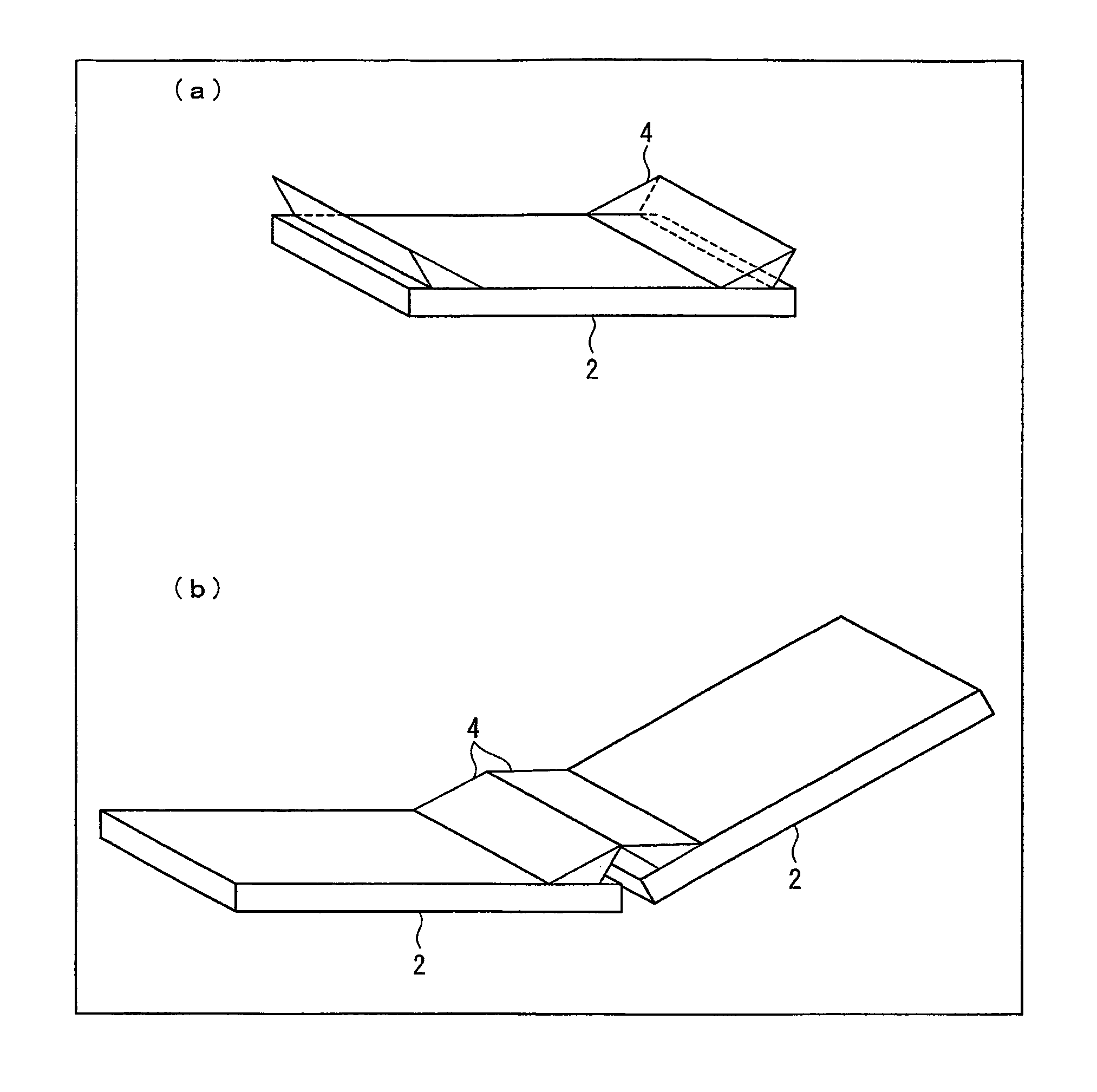
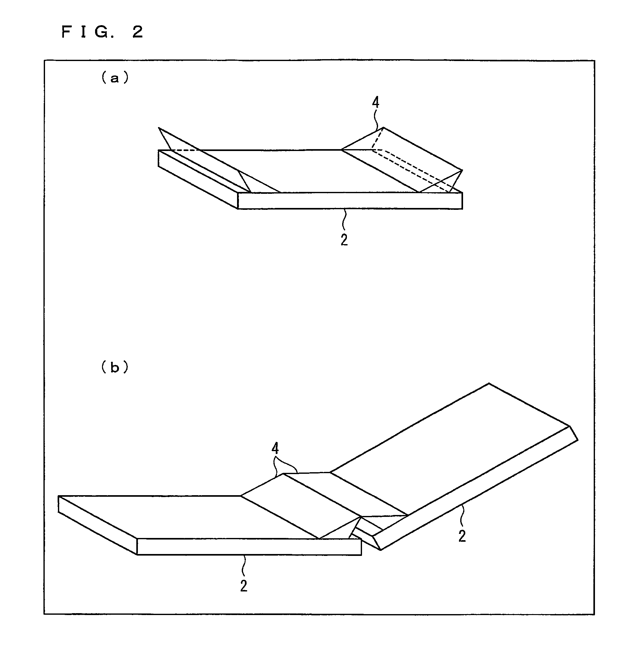
[0039]FIG. 2 is a perspective view illustrating an outline arrangement of a liquid crystal display device (display device) of the present embodiment. Each of the liquid crystal display devices shown in (a) and (b) of FIG. 2 includes a liquid crystal display panel(s) 2 and light guide elements 4. The liquid crystal display device shown in (a) of FIG. 2 includes a liquid crystal display panel 2 having a rectangular shape and two light guide elements 4 provided on the liquid crystal display panel 2 so as to be located in right and left peripheral areas facing each other out of peripheral areas of the liquid crystal display panel 2. Meanwhile, the liquid crystal display device ...

embodiment 2

[0112]Another embodiment of the present invention is described below with reference to FIGS. 11 through 18. For convenience of description, constituent members having the identical functions to those shown in the drawings of Embodiment 1 are given identical reference numerals, and are not explained repeatedly.

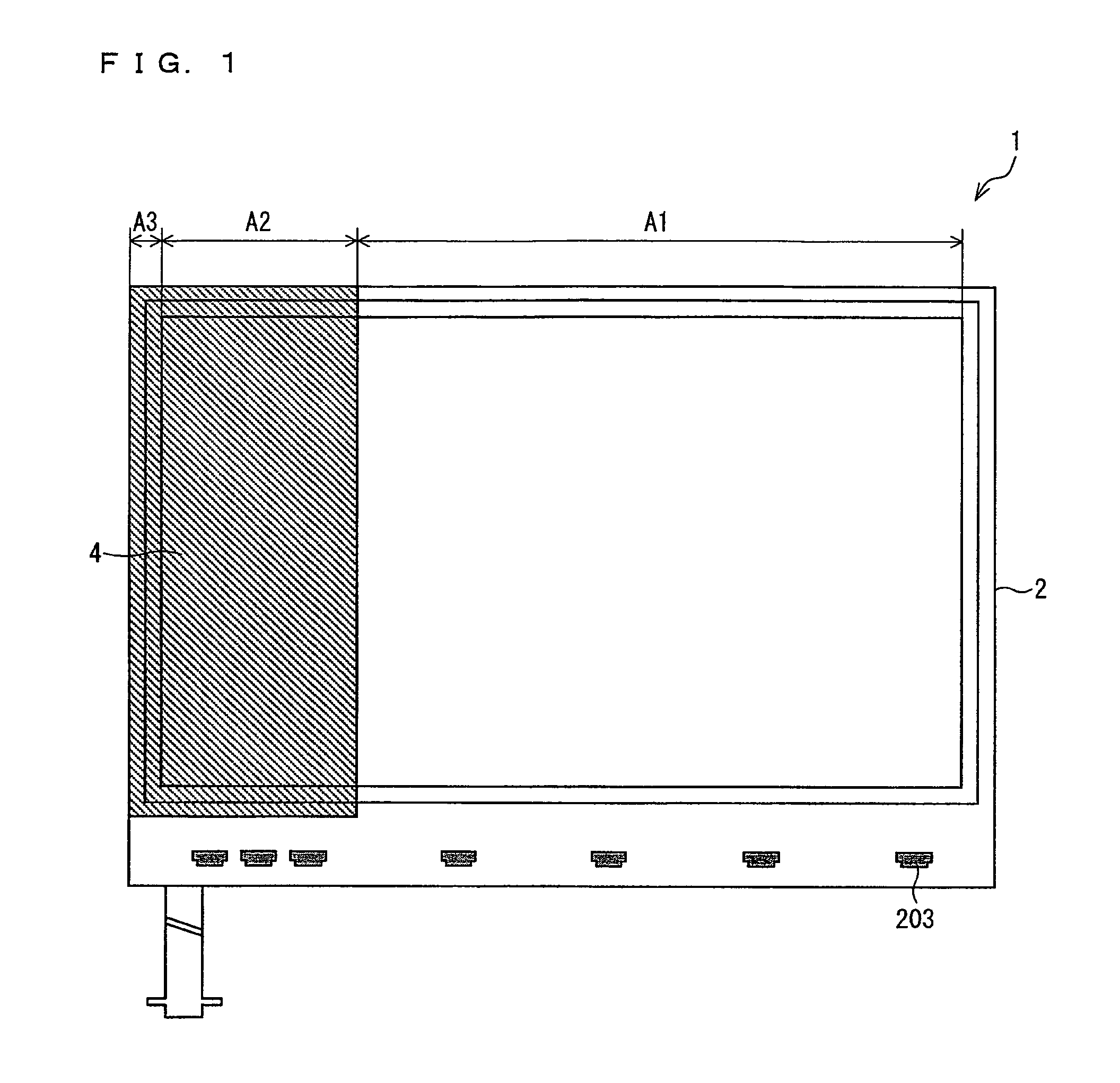
[0113]According to Embodiment 1, the following problem occurs in a case where surface luminance of the liquid crystal display device in the display area end portion A2 at maximum gradation is set to match surface luminance of the liquid crystal display device in the normal display area A1 at maximum gradation. Specifically, since backlight luminance in the display area end portion A2 is increased, a black image (gradation 0) for example is brighter in the display area end portion A2 than in the normal display area A1 as shown in FIG. 11. This gives a viewer a sense of strangeness.

[0114]For example, FIG. 11 shows that surface luminance of approximately 4 cd / m2 is observed in the...


PUM


Abstract

Provided is a display device for carrying out seamless display so that a sense of strangeness is not given to a viewer or the sense of strangeness is reduced. In at least one example embodiment, a display device that displays an image based on image signals DAT, includes: a display panel having (i) a display area in which a plurality of display elements for displaying the image are disposed in a matrix and (ii) a frame area which is located at an end of the display panel and in which no display element is provided; a backlight device which emits light, in a form of plane emission, towards a surface opposite to a display surface of the display area; and a light guide element which is provided on the display panel and which changes a light path of part of light emitted from the plurality of display elements so that the part of light is guided to the frame area, and luminance per unit area in a light-emitting surface of the backlight device is larger in a display area end portion where the light guide element is provided than in a normal display area where the light guide element is not provided out of the display area.

Description

TECHNICAL FIELD[0001]The present invention relates to a display device and a display method. More specifically, the present invention relates to a display device (hereinafter referred to as seamless display) and a display method, in each of which a seamless screen is achieved with the use of a plurality of display panels.BACKGROUND ART[0002]In recent years, there is an increasing demand for a light and thin display. Especially, active matrix type liquid crystal display devices using a large liquid crystal panel are in wide spread use. However, an increase in size of a liquid crystal panel poses many technical restrictions. In view of this, attempts have been conventionally made for seemingly increasing a size of a liquid crystal panel by combining a plurality of display devices.[0003]However, since each of the display devices has a frame region, the attempts cause a problem that seams between the plurality of display devices are visible. This problem is not a problem specific to liq...

Claims


Application Information

Patent Timeline
Patent Type & Authority Patents(United States)
IPC IPC(8): G09G3/36
CPCG09G2320/0271G09G2310/0232G09G2320/0285G09G2320/0233G02F1/13336G09G3/3611G02F1/133524G09G2300/026G09G3/342G09G2320/0646G09G2320/0276G09G2320/0633G09G2320/0238G09G2360/16
Inventor IMAMURA, KENTAROUYOSHIDA, SHIGETO
Owner SHARP KK
Why Eureka
Try Eureka