
Plasma display device and driving method thereof

Inactive Publication Date: 2008-05-29
SAMSUNG SDI CO LTD
View PDF7 Cites 0 Cited by
  • Summary
  • Abstract
  • Description
  • Claims
  • Application Information

AI Technical Summary

Benefits of technology

[0008]Accordingly, an aspect of the invention is to provide a plasma display device and a driving method thereof that can generate a stable discharge and compensate for a reduction in luminance.
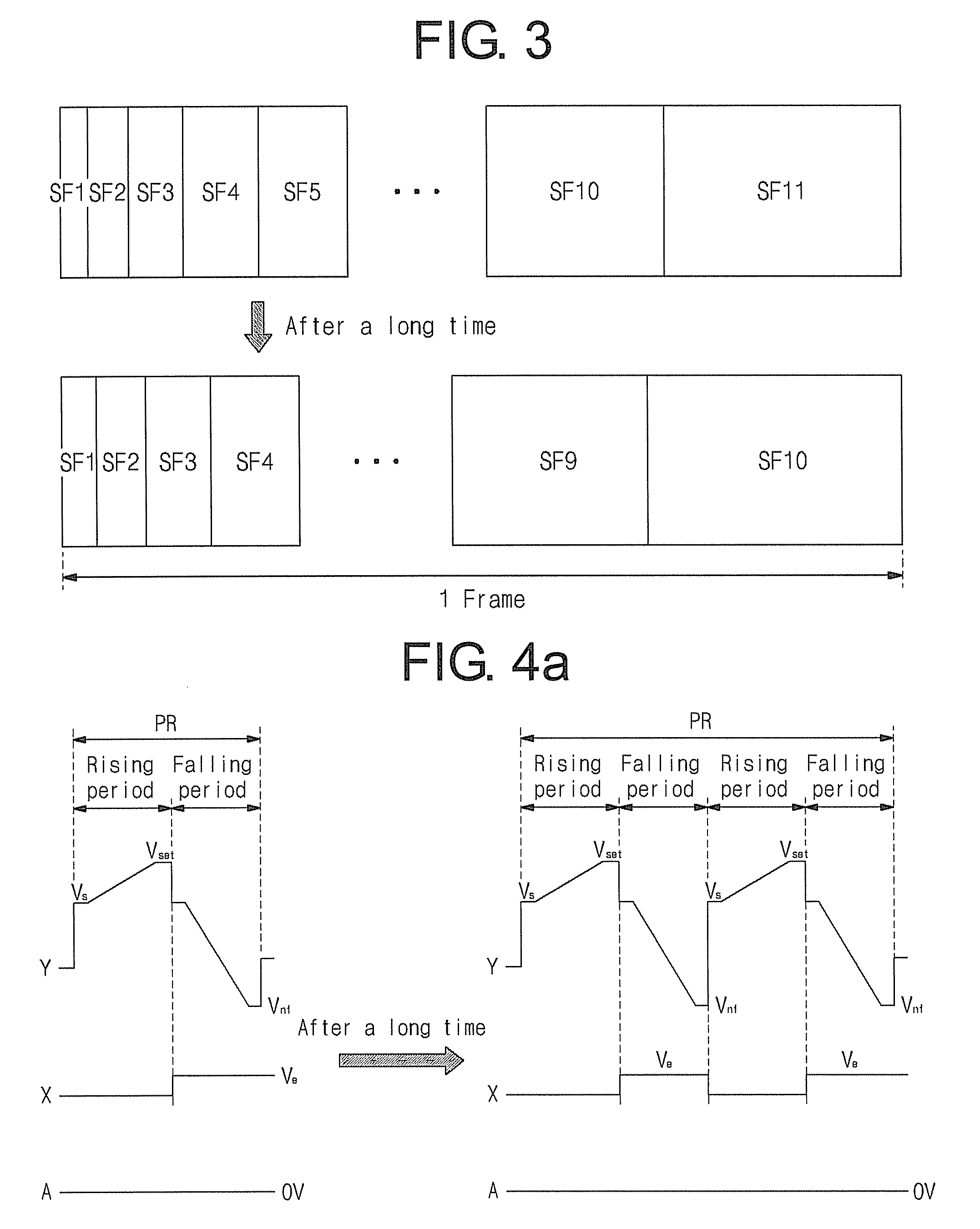
[0010]The changing of a number of the sub-fields in one frame may include checking whether the cumulative operating time of the plasma display device has exceeded a critical time; and reducing the number of the sub-fields in one frame when the cumulative operating time has exceeded the critical time to a number of sub-fields that is less than the number of the sub-fields in one frame when the cumulative operating time has not exceeded the critical time.
[0015]The controller may include a time checker to check whether the cumulative operating time of the plasma display device has exceeded a critical time; and a sub-field generator to reduce the number of the sub-fields in one frame when the cumulative operating time has exceeded the critical time to a number of sub-fields that is less than the number of sub-fields in one frame when the cumulative operating time has not exceeded the critical time.

Problems solved by technology

When the PDP has been operated for a long time, a protective layer, a phosphor, and the like inside the PDP deteriorate.
Accordingly, the PDP suffers from a problem wherein a discharge characteristic, especially a luminance, is reduced in a PDP that has been operated for a long time compared to a PDP that has been operated for a short time.

Method used


Image

  • Plasma display device and driving method thereof
  • Plasma display device and driving method thereof
  • Plasma display device and driving method thereof

Examples


Embodiment Construction

[0034]Reference will now be made in detail to embodiments of the invention, examples of which are shown in the accompanying drawings, wherein like reference numerals refer to like elements throughout. The embodiments are described below by referring to the figures.

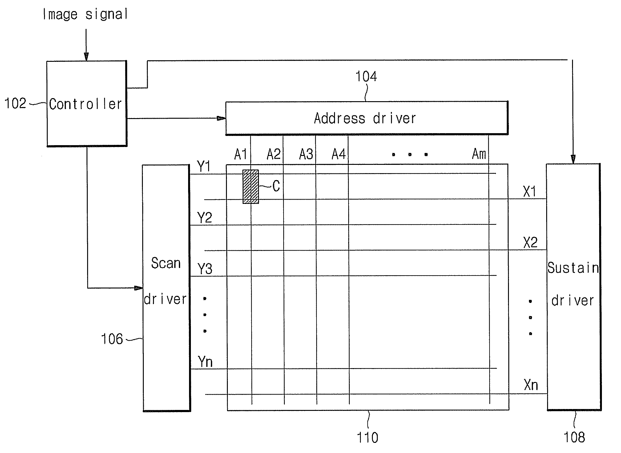
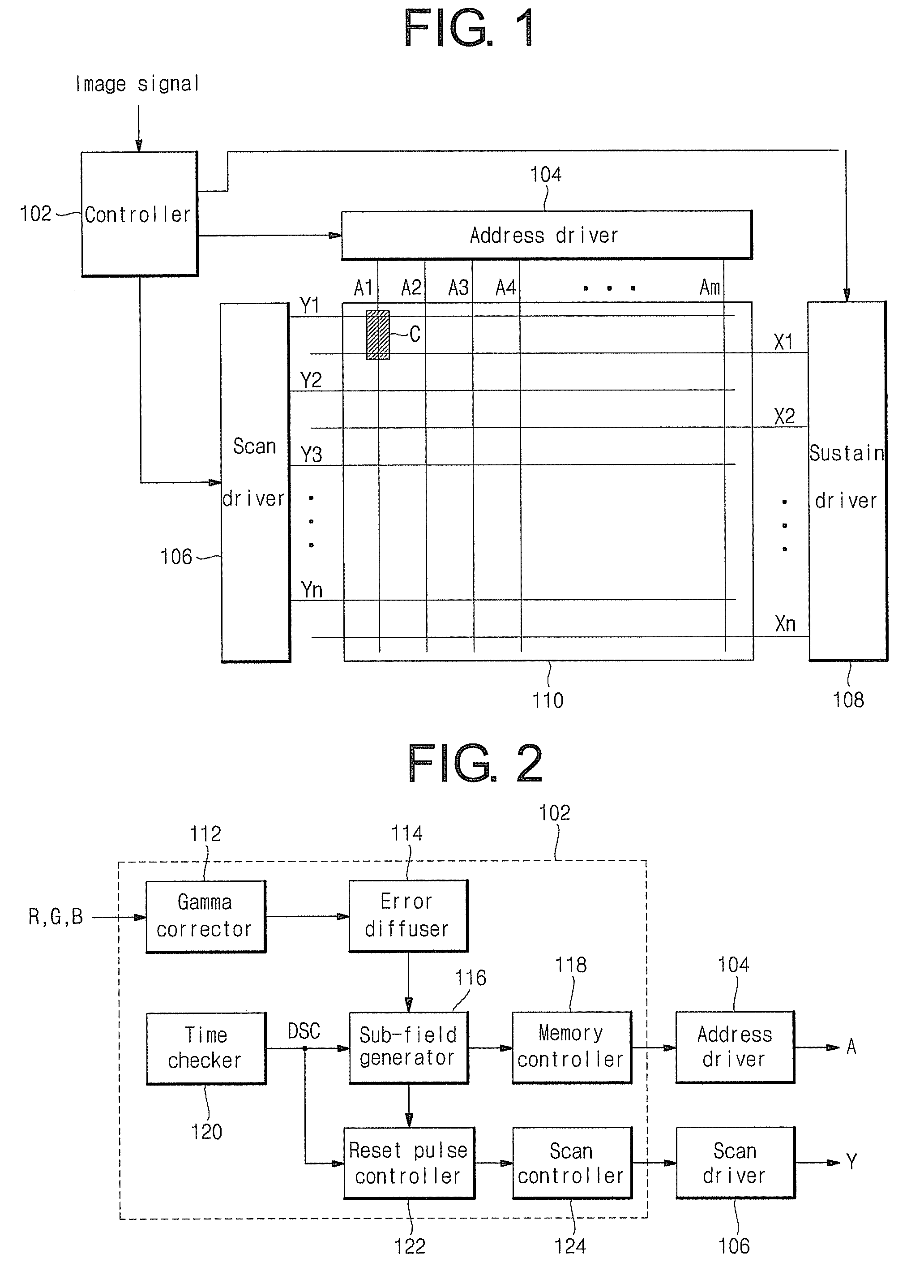
[0035]FIG. 1 is a block diagram of a plasma display device according to a first aspect of the invention.

[0036]Referring to FIG. 1, the plasma display device includes a plasma display panel (PDP or panel) 110 displaying an image, an address driver 104 supplying data to address electrodes (A1 to Am) of the PDP 110, a scan driver 106 driving scan electrodes (Y1 to Yn) of the PDP 110, a sustain driver 108 driving sustain electrodes (X1 to Xn) of the PDP 110, and a controller 102 controlling the drivers 104, 106, and 108.

[0037]The PDP 110 displays an image using a plurality of discharge cells (C) arranged in a matrix. The discharge cells (C) are at intersections of the address electrodes (A1 to Am) extending in the column direc...


PUM


Abstract

A method of driving a plasma display device wherein one frame is divided into a plurality of sub-fields each including a reset period, an address period, and a sustain period, and a gray level is expressed by a combination of weight values of luminances of the sub-fields. The method includes changing a number of the sub-fields in one frame based on a cumulative operating time of the plasma display device; and changing a width, and / or a slope, and / or a number of a reset pulse supplied to a plasma display panel of the plasma display device in the reset period, and / or a scan pulse supplied to the plasma display panel in the address period, and / or a sustain pulse supplied to the plasma display panel in the sustain period when the number of the sub-fields in one frame is changed.

Description

CROSS-REFERENCE TO RELATED APPLICATIONS[0001]This application claims the benefit of Korean Patent Application No. 2006-117889 filed on Nov. 27, 2006, in the Korean Intellectual Property Office, the disclosure of which is incorporated herein by reference in its entirety.BACKGROUND OF THE INVENTION[0002]1. Field of the Invention[0003]An aspect of the invention relates to a plasma display device and a driving method thereof, and more particularly to a plasma display device and a driving thereof that can generate a stable electric discharge and compensate for a reduction in luminance.[0004]2. Description of the Related Art[0005]Generally, a plasma display device is a display device using a plasma display panel (hereafter referred to as a “PDP”) for displaying text or an image using a plasma generated by a gas discharge.[0006]The PDP is driven by dividing one frame into a plurality of sub-fields each having a respective weight value. A state of a discharge cell is initialized during a re...

Claims


Application Information

Patent Timeline
IPC IPC(8): G09G3/28
CPCG09G3/2022G09G3/2927G09G3/293G09G2360/16G09G2310/066G09G2320/048G09G3/2944G09G3/291G09G3/296
Inventor CHAE, SEUNGHUN
Owner SAMSUNG SDI CO LTD
Learn More